
Page 457 - Dynamics of Mechanical Systems
P. 457
0593_C12_fm Page 438 Monday, May 6, 2002 3:11 PM
438 Dynamics of Mechanical Systems
D
Y
O
Ω
β 1
1
β
S
2
β
2
α
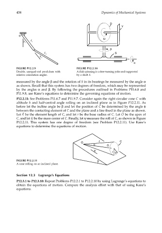
FIGURE P12.2.9 FIGURE P12.2.10
Double, unequal-rod pendulum with A disk spinning in a free-turning yoke and supported
relative orientation angles. by a shaft S.
measured by the angle β and the rotation of S in its bearings be measured by the angle α
as shown. Recall that this system has two degrees of freedom, which may be represented
by the angles α and β. By following the procedures outlined in Problems P11.6.8 and
P11.9.8, use Kane’s equations to determine the governing equations of motion.
P12.2.11: See Problems P11.6.7 and P11.9.7. Consider again the right circular cone C with
altitude h and half-central angle rolling on an inclined plane as in Figure P12.2.11. As
before let the incline angle be β and let the position of C be determined by the angle φ
between the contacting element of C and the plane and a line fixed in the plane as shown.
Let be the element length of C, and let r be the base radius of C. Let O be the apex of
C, and let G be the mass center of C. Finally, let ψ measure the roll of C, as shown in Figure
P12.2.11. This system has one degree of freedom (see Problem P12.2.11). Use Kane’s
equations to determine the equations of motion.
C
O
α G
φ
r ψ
FIGURE P12.2.11 β
A cone rolling on an inclined plane.
Section 12.3 Lagrange’s Equations
P12.3.1 to P12.3.10: Repeat Problems P12.2.1 to P12.2.10 by using Lagrange’s equations to
obtain the equations of motion. Compare the analysis effort with that of using Kane’s
equations.