
Page 515 - Dynamics of Mechanical Systems
P. 515
0593_C14_fm Page 496 Tuesday, May 7, 2002 6:56 AM
496 Dynamics of Mechanical Systems
T *
D N 3
F *
Q
Q w
G
ω F *
G
C
N 1
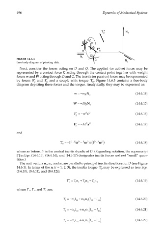
FIGURE 14.6.3 C N
Free-body diagram of pivoting disk. 2
Next, consider the forces acting on D and Q. The applied (or active) forces may be
represented by a contact force C acting through the contact point together with weight
forces w and W acting through Q and G. The inertia (or passive) forces may be represented
by forces F * and F * and a couple with torque T * . Figure 14.6.3 contains a free-body
Q G D
diagram depicting these forces and the torque. Analytically, they may be expressed as:
w =−mg N (14.6.14)
3
W =−Mg N (14.6.15)
3
F =− m RQ (14.6.16)
a
*
Q
F =− M RG (14.6.17)
*
a
D
and
T =− I ⋅ αα D − ωω D ×( I ⋅ ωω D ) (14.6.18)
D
R
R
D
R
*
D
where as before, I is the central inertia dyadic of D. (Regarding notation, the superscript
D
[ ] in Eqs. (14.6.15), (14.6.16), and (14.5.17) designates inertia forces and not “small” quan-
*
tities.)
The unit vectors n , n , and n are parallel to principal inertia directions for D (see Figure
1 2 3
14.6.1). In terms of the n (i = 1, 2, 3), the inertia torque T * may be expressed as (see Eqs.
i D
(8.6.10), (8.6.11), and (8.6.12)):
T = T n + T n + T n (14.6.19)
*
D 1 1 2 2 3 3
where T , T , and T are:
1 2 3
2 (
T =−α I + ω ω I − ) (14.6.20)
I
1 1 11 3 22 33
3 (
T =−α I + ω ω I − ) (14.6.21)
I
2 2 22 1 33 11
1 (
T =−α I + ω ω I − ) (14.6.22)
I
3 3 33 2 11 22