
Page 561 - Dynamics of Mechanical Systems
P. 561
0593_C16_fm Page 542 Tuesday, May 7, 2002 7:06 AM
542 Dynamics of Mechanical Systems
FIGURE 16.3.1
A radial cam–follower pair.
Follower
Cam Normal
Trace Point
Direction of Follower Wheel
Follower Motion
Cam Profile
Pitch Curve
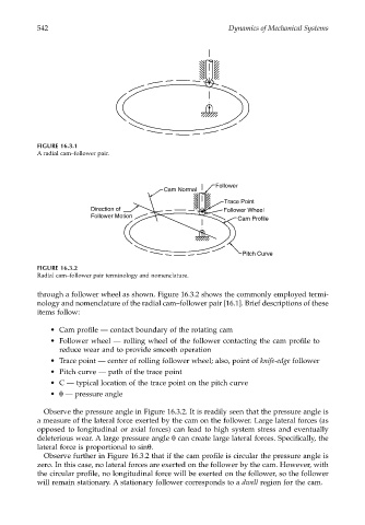
FIGURE 16.3.2
Radial cam–follower pair terminology and nomenclature.
through a follower wheel as shown. Figure 16.3.2 shows the commonly employed termi-
nology and nomenclature of the radial cam–follower pair [16.1]. Brief descriptions of these
items follow:
• Cam profile — contact boundary of the rotating cam
• Follower wheel — rolling wheel of the follower contacting the cam profile to
reduce wear and to provide smooth operation
• Trace point — center of rolling follower wheel; also, point of knife-edge follower
• Pitch curve — path of the trace point
• C — typical location of the trace point on the pitch curve
• θ — pressure angle
Observe the pressure angle in Figure 16.3.2. It is readily seen that the pressure angle is
a measure of the lateral force exerted by the cam on the follower. Large lateral forces (as
opposed to longitudinal or axial forces) can lead to high system stress and eventually
deleterious wear. A large pressure angle θ can create large lateral forces. Specifically, the
lateral force is proportional to sinθ.
Observe further in Figure 16.3.2 that if the cam profile is circular the pressure angle is
zero. In this case, no lateral forces are exerted on the follower by the cam. However, with
the circular profile, no longitudinal force will be exerted on the follower, so the follower
will remain stationary. A stationary follower corresponds to a dwell region for the cam.