
Page 566 - Dynamics of Mechanical Systems
P. 566
0593_C16_fm Page 547 Tuesday, May 7, 2002 7:06 AM
Mechanical Components: Cams 547
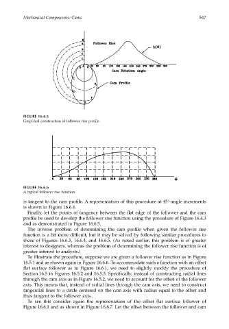
FIGURE 16.6.5
Graphical construction of follower rise profile.
FIGURE 16.6.6
A typical follower rise function.
is tangent to the cam profile. A representation of this procedure at 45°-angle increments
is shown in Figure 16.6.4.
Finally, let the points of tangency between the flat edge of the follower and the cam
profile be used to develop the follower rise function using the procedure of Figure 16.4.3
and as demonstrated in Figure 16.6.5.
The inverse problem of determining the cam profile when given the follower rise
function is a bit more difficult, but it may be solved by following similar procedures to
those of Figures 16.6.3, 16.6.4, and 16.6.5. (As noted earlier, this problem is of greater
interest to designers, whereas the problem of determining the follower rise function is of
greater interest to analysts.)
To illustrate the procedure, suppose we are given a follower rise function as in Figure
16.5.1 and as shown again in Figure 16.6.6. To accommodate such a function with an offset
flat surface follower as in Figure 16.6.1, we need to slightly modify the procedure of
Section 16.5 in Figures 16.5.2 and 16.5.3. Specifically, instead of constructing radial lines
through the cam axis as in Figure 16.5.2, we need to account for the offset of the follower
axis. This means that, instead of radial lines through the cam axis, we need to construct
tangential lines to a circle centered on the cam axis with radius equal to the offset and
thus tangent to the follower axis.
To see this consider again the representation of the offset flat surface follower of
Figure 16.6.1 and as shown in Figure 16.6.7. Let the offset between the follower and cam