
Page 564 - Dynamics of Mechanical Systems
P. 564
0593_C16_fm Page 545 Tuesday, May 7, 2002 7:06 AM
Mechanical Components: Cams 545
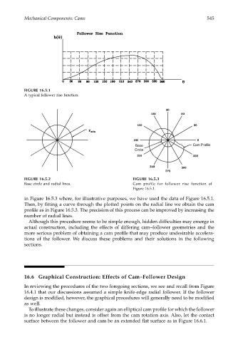
FIGURE 16.5.1
A typical follower rise function.
Base Cam Profile
Circle
FIGURE 16.5.2 FIGURE 16.5.3
Base circle and radial lines. Cam profile for follower rise function of
Figure 16.5.1.
in Figure 16.5.3 where, for illustrative purposes, we have used the data of Figure 16.5.1.
Then, by fitting a curve through the plotted points on the radial line we obtain the cam
profile as in Figure 16.5.3. The precision of this process can be improved by increasing the
number of radial lines.
Although this procedure seems to be simple enough, hidden difficulties may emerge in
actual construction, including the effects of differing cam–follower geometries and the
more serious problem of obtaining a cam profile that may produce undesirable accelera-
tions of the follower. We discuss these problems and their solutions in the following
sections.
16.6 Graphical Construction: Effects of Cam–Follower Design
In reviewing the procedures of the two foregoing sections, we see and recall from Figure
16.4.1 that our discussions assumed a simple knife-edge radial follower. If the follower
design is modified, however, the graphical procedures will generally need to be modified
as well.
To illustrate these changes, consider again an elliptical cam profile for which the follower
is no longer radial but instead is offset from the cam rotation axis. Also, let the contact
surface between the follower and cam be an extended flat surface as in Figure 16.6.1.