
Page 562 - Dynamics of Mechanical Systems
P. 562
0593_C16_fm Page 543 Tuesday, May 7, 2002 7:06 AM
Mechanical Components: Cams 543
These observations show that there is no follower movement without a nonzero pressure
angle; hence, a cost of follower movement is the lateral force generated by the pressure angle.
Thus, cam designers generally attempt to obtain the desired follower motion with the smallest
possible pressure angle. This is usually accomplished by a large cam, as space permits.
Finally, observe that the follower wheel simply has the effect of enlarging the cam profile
creating the pitch curve, with the follower motion then defined by the movement of the
trace point.
16.4 Graphical Constructions: The Follower Rise Function
The central problem confronting the cam designer is to determine the cam profile that
will produce a desired follower movement. To illustrate these concepts and some graphical
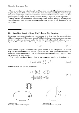
design procedures, consider again the simple knife-edge radial follower pair of
Figure 16.4.1. Let the cam profile be represented analytically as (see Figure 16.4.2):
r = () θ (16.4.1)
f
where r and θ are polar coordinates of a typical point P on the cam profile. The angle θ
may also be identified with the rotation angle of the cam. Thus, given f(θ), we know r as
a function of the rotation angle. Then with the knife-edge follower, we can identify r with
the movement of the follower.
θ
˙
If the angular speed ω of the cam (ω = ) is constant, the speed v of the follower is:
df dθ df
v == dr dt = df dt = = ω (16.4.2)
r ˙
θ
d dt dθ
and the acceleration a of the follower is:
d df d df
a == ω = ω
r ˙˙
dt d dt d
θ
θ
(16.4.3)
d df dθ df
2
= ω θ d dt = ω 2 dθ 2
d θ
Y
r P
θ
O X
FIGURE 16.4.1 FIGURE 16.4.2
Knife-edge radial cam–follower pair. Polar coordinates of a cam profile.