
Page 567 - Dynamics of Mechanical Systems
P. 567
0593_C16_fm Page 548 Tuesday, May 7, 2002 7:06 AM
548 Dynamics of Mechanical Systems
ρ
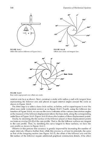
FIGURE 16.6.7 FIGURE 16.6.8
Offset flat surface follower of Figure 16.6.1. Offset axes circle and tangent line.
FIGURE 16.6.9
Base circle superposed over offset axis circle.
rotation axis be ρ as shown. Next, construct a circle with radius ρ and with tangent lines
representing the follower axis and placed at equal interval angles around the circle as
shown in Figure 16.6.8.
The third step is to select a base circle radius, as before, and to superimpose it over the
offset axes circle (coincident centers) as in Figure 16.6.9. Fourth, using the follower rise
function of Figure 16.6.6, we can use the curve ordinates of the various cam rotation angles
as the measure of the follower displacement above the base circle, along the corresponding
radial lines of Figure 16.6.9. Figure 16.6.10 shows the location of these displacement points.
Finally, by sketching the flat surface of the follower placed at these displacement points
we form an envelope [16.2] of the cam profile. That is, the flat follower surfaces are tangent
to the cam profile. Then, by sketching the curve tangent to these surfaces, we have the
cam profile as shown in Figure 16.6.11.
Observe in this process that accuracy is greatly improved by increasing the number of
angle intervals. Observe further that, while this process is, at least in principle, the same
as that of the foregoing section (see Figure 16.5.3), the offset of the follower axis and the
flat surface of the follower require additional graphical construction details. (One effect