
Page 568 - Dynamics of Mechanical Systems
P. 568
0593_C16_fm Page 549 Tuesday, May 7, 2002 7:06 AM
Mechanical Components: Cams 549
FIGURE 16.6.10
Follower displacement points relative to the base circle.
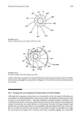
FIGURE 16.6.11
Envelope of follower flat defining the cam profile.
of this is that the cam profile can fall inside the base circle as seen in Figure 16.6.11.) Finally,
observe that, although the cam profiles of Figures 16.5.3 and 16.6.11 are not identical, they
are similar.
16.7 Comments on Graphical Construction of Cam Profiles
Although the foregoing constructions are conceptually relatively simple, difficulties are
encountered in implementing them. First, because they are graphical constructions, their
accuracy is somewhat limited — although emerging computer graphics techniques will
undoubtedly provide a means for improving the accuracy. Next, analyses assuming point
contact between the cam and follower (as in Sections 16.4 and 16.5) may produce cam
profiles that are either impractical or incompatible with roller-tipped followers. For exam-
ple, for an arbitrary follower rise function, it is possible to obtain cam profiles with cusps
or concavities as in Figure 16.7.1. Finally, if the cam is rotating rapidly (as is often the