
Page 569 - Dynamics of Mechanical Systems
P. 569
0593_C16_fm Page 550 Tuesday, May 7, 2002 7:06 AM
550 Dynamics of Mechanical Systems
(a) (b)
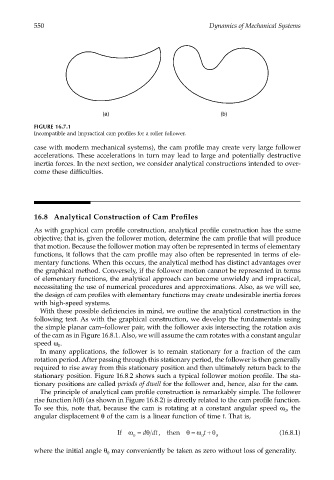
FIGURE 16.7.1
Incompatible and impractical cam profiles for a roller follower.
case with modern mechanical systems), the cam profile may create very large follower
accelerations. These accelerations in turn may lead to large and potentially destructive
inertia forces. In the next section, we consider analytical constructions intended to over-
come these difficulties.
16.8 Analytical Construction of Cam Profiles
As with graphical cam profile construction, analytical profile construction has the same
objective; that is, given the follower motion, determine the cam profile that will produce
that motion. Because the follower motion may often be represented in terms of elementary
functions, it follows that the cam profile may also often be represented in terms of ele-
mentary functions. When this occurs, the analytical method has distinct advantages over
the graphical method. Conversely, if the follower motion cannot be represented in terms
of elementary functions, the analytical approach can become unwieldy and impractical,
necessitating the use of numerical procedures and approximations. Also, as we will see,
the design of cam profiles with elementary functions may create undesirable inertia forces
with high-speed systems.
With these possible deficiencies in mind, we outline the analytical construction in the
following text. As with the graphical construction, we develop the fundamentals using
the simple planar cam–follower pair, with the follower axis intersecting the rotation axis
of the cam as in Figure 16.8.1. Also, we will assume the cam rotates with a constant angular
speed ω .
0
In many applications, the follower is to remain stationary for a fraction of the cam
rotation period. After passing through this stationary period, the follower is then generally
required to rise away from this stationary position and then ultimately return back to the
stationary position. Figure 16.8.2 shows such a typical follower motion profile. The sta-
tionary positions are called periods of dwell for the follower and, hence, also for the cam.
The principle of analytical cam profile construction is remarkably simple. The follower
rise function h(θ) (as shown in Figure 16.8.2) is directly related to the cam profile function.
To see this, note that, because the cam is rotating at a constant angular speed ω , the
0
angular displacement θ of the cam is a linear function of time t. That is,
θ
=
t
If ω = ddt, then θ ω + θ (16.8.1)
0 0 0
where the initial angle θ may conveniently be taken as zero without loss of generality.
0