
Page 598 - Dynamics of Mechanical Systems
P. 598
0593_C17_fm Page 579 Tuesday, May 7, 2002 7:12 AM
Mechanical Components: Gears 579
Involute
Belt
Pulley
FIGURE 17.4.3 FIGURE 17.4.4
Pitch circle and base circle radii. Belt unwrapping around a fixed pulley.
Y
P(x,y)
Involute
n y
r
Q Generating
Base Tangent Line
θ c
Circle β
r
φ b T
θ γ
X
O
n x
FIGURE 17.4.5
Involute curve geometry.
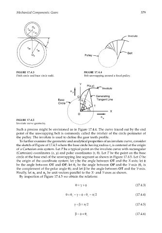
Such a process might be envisioned as in Figure 17.4.4. The curve traced out by the end
point of the unwrapping belt is commonly called the involute of the circle perimeter of
the pulley. The involute is used to define the gear tooth profile.
To further examine the geometric and analytical properties of an involute curve, consider
the sketch of Figure of 17.4.5 where the base circle having radius r is centered at the origin
b
of a Cartesian axis system. Let P be a typical point on the involute curve with rectangular
(Cartesian) coordinates (x, y) and polar coordinates (r, θ). Let T be the point on the base
circle at the base end of the unwrapping line segment as shown in Figure 17.4.5. Let O be
the origin of the coordinate system; let γ be the angle between OT and the X-axis; let φ
be the angle between OT and OP; let θ be the angle between OP and the Y-axis (θ is
C
C
the complement of the polar angle θ); and let β be the angle between OT and the Y-axis.
Finally, let n and n be unit vectors parallel to the X- and Y-axes as shown.
x
y
By inspection of Figure 17.4.5 we obtain the relations:
θ =+ φ (17.4.3)
γ
+
θθ = + φ θ = π 2 (17.4.4)
+
γ
c c
γβ+= π 2 (17.4.5)
β =+ (17.4.6)
φ θ
c