
Page 97 - Dynamics of Mechanical Systems
P. 97
0593_C04*_fm Page 78 Monday, May 6, 2002 2:06 PM
78 Dynamics of Mechanical Systems
n
3
n
2
N
3
n
1
R
B
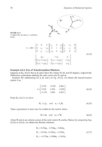
FIGURE 4.2.1
N 2
A rigid body moving in a reference
frame. N 1
1 0 0 c β 0 s c γ s − γ 0
β
S = ABC = 0 c α s − α 0 1 0 s c γ 0
γ
0 s α c − s β 0 c 0 0 1
β
α
(4.2.3)
cc − c s s
β γ β γ β
c c −
cs +
= ( αγ s s c ) ( α γ s s s ) −ssc
α β
α β γ
α β γ
ss − c s c ) ( s c + c s s )
α β
( αγ α β γ α γ α β γ cc
Example 4.2.1: Use of Transformation Matrices
Suppose in Eq. (4.2.3) that α, β, and γ have the values 30, 60, and 45 degrees, respectively.
Determine expressions relating the unit vector sets N and n .
i i
Solution: By substituting for α, β, and γ in Eq. (4.2.3), we obtain the transformation
matrix S as:
.
0 354. −0 354. 0 866
.
S = 0 918. 0 306 −0 250. (4.2.4)
.
.
− 0 176. 0 884 0 433
From Eq. (4.2.1) we have:
N = S n and n = S N (4.2.5)
i ij j i ji j
These expressions in turn may be written in the matrix forms:
n
N = S and n = S T N (4.2.6)
where N and n are column arrays of the unit vectors N and n . Hence, by comparing Eqs.
i
i
(4.2.4) to (4.2.6), we obtain the desired relations:
0 866
0 354
N = . n − . n + . n
0 354
1 1 2 3
0 918
N = . n + . n − . n (4.2.7)
0 306
0 250
2 1 2 3
0 176
0 433
N =− . n + . n + . n
0 884
3 1 2 3