
Page 98 - Dynamics of Mechanical Systems
P. 98
0593_C04*_fm Page 79 Monday, May 6, 2002 2:06 PM
Kinematics of a Rigid Body 79
and
0 918
0 354
n = . N + . N − . N
0 176
1 1 2 3
n =− . N + . N + . N (4.2.8)
0 884
0 354
0 306
2 1 2 3
0 866
0 250
0 433
n = . N − . N + . N
3 1 2 3
Just as S defines the relative inclinations of the n and the N it also defines the relative
j
i,
inclination or orientation of B and R. In this context the angles α, β, and γ are called
orientation angles. We will find these concepts to be useful in our discussion about angular
velocity. Before we consider that, however, it is useful to consider a procedure for deter-
mining the transformation matrices for various orientation angle sets. We do this in the
following section.
4.3 Configuration Graphs
Consider again the problem of relating unit vector sets to each other — that is, expressing
the vectors of one set in terms of the vectors in the other set (see Section 2.11). As before,
ˆ
let N (i = 1, 2, 3) and ΝΝ j (j = 1, 2, 3) be mutually perpendicular dextral unit vector sets,
i
ˆ
and let N and ΝΝ be aligned with each other. Let the remaining vectors be inclined relative
i 1
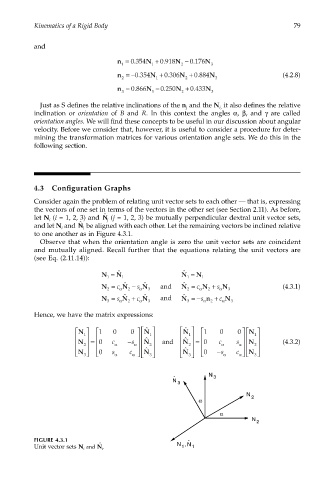
to one another as in Figure 4.3.1.
Observe that when the orientation angle is zero the unit vector sets are coincident
and mutually aligned. Recall further that the equations relating the unit vectors are
(see Eq. (2.11.14)):
ˆ
ˆ
N = N 1 N = N 1
1
1
ˆ
ˆ
ˆ
N = c α N − s α N 3 and N = c α N + s α N 3 (4.3.1)
2
2
2
2
ˆ
ˆ
ˆ
N = s N + c N and N =−s n + c N
3 α 2 α 3 3 α 2 α 3
Hence, we have the matrix expressions:
N
N
N 1 0 0 ˆ ˆ 1 0 0 N
1 ˆ 1 ˆ 1 1
2
N 2 = 0 c α −s α N and N 2 = 0 c α s α N 2 (4.3.2)
N 0 s α c α ˆ 3 ˆ 3 0 −s α c α N
N
N
3
3
N
ˆ 3
N 3
N
2
α
α
N
2
FIGURE 4.3.1 ˆ
,
ˆ N N
Unit vector sets N i and N i . 1 1