
Page 99 - Dynamics of Mechanical Systems
P. 99
0593_C04*_fm Page 80 Monday, May 6, 2002 2:06 PM
80 Dynamics of Mechanical Systems
ˆ
i N i N i
N
1
2
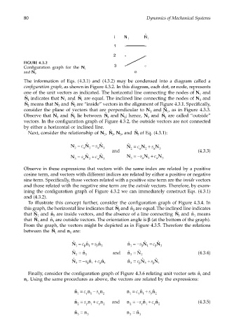
FIGURE 4.3.2
3
Configuration graph for the N i
ˆ
and N i . α
The information of Eqs. (4.3.1) and (4.3.2) may be condensed into a diagram called a
configuration graph, as shown in Figure 4.3.2. In this diagram, each dot, or node, represents
one of the unit vectors as indicated. The horizontal line connecting the nodes of N and
1
ˆ
ˆ
ΝΝ 1 indicates that N and ΝΝ 1 are equal. The inclined line connecting the nodes of N and
3
1
ΝΝ 2 means that N and ΝΝ 2 are “inside” vectors in the alignment of Figure 4.3.1. Specifically,
ˆ
ˆ
3
ˆ
consider the plane of vectors that are perpendicular to N and N 1 , as in Figure 4.3.3.
1
ˆ
ˆ
Observe that N and ΝΝ lie between ΝΝ and N ; hence, N and ΝΝ are called “outside”
ˆ
3 2 3 2 3 2
vectors. In the configuration graph of Figure 4.3.2, the outside vectors are not connected
by either a horizontal or inclined line.
ˆ
Next, consider the relationship of N , ΝΝ 2 , N , and ΝΝ 3 of Eq. (4.3.1):
ˆ
3
2
ˆ
ˆ
ˆ
N = c N − s N N = c N + s N
2 α 2 α 3 2 α 2 α 3
and (4.3.3)
ˆ
ˆ
N = s N + c N N =−s α N + c α N
3 α 2 α 3 3 2 3
Observe in these expressions that vectors with the same index are related by a positive
cosine term, and vectors with different indices are related by either a positive or negative
sine term. Specifically, those vectors related with a positive sine term are the inside vectors
and those related with the negative sine term are the outside vectors. Therefore, by exam-
ining the configuration graph of Figure 4.3.2 we can immediately construct Eqs. (4.3.1)
and (4.3.2).
To illustrate this concept further, consider the configuration graph of Figure 4.3.4. In
this graph, the horizontal line indicates that ΝΝ 2 and are equal. The inclined line indicates
ˆ
ˆ n
2
ˆ
ˆ are inside vectors, and the absence of a line connecting ΝΝ
that N 1 and ˆ n 3 3 and ˆ n 1 means
ˆ
that ΝΝ 3 and ˆ n 1 are outside vectors. The orientation angle is β (at the bottom of the graph).
From the graph, the vectors might be depicted as in Figure 4.3.5. Therefore the relations
between the ΝΝ 1 and n are:
ˆ
1
ˆ
ˆ
ˆ
N = c β ˆ n + s β ˆ n 3 ˆ n =−s β N + c β N 3
1
1
1
1
ˆ
N = ˆ n and ˆ n = N (4.3.4)
ˆ
2 2 2 2
ˆ
ˆ
ˆ
N =−s β ˆ n + c β ˆ n 1 ˆ n = c β N + s β N 1
3
3
1
3
Finally, consider the configuration graph of Figure 4.3.6 relating unit vector sets and
ˆ n
i
n . Using the same procedures as above, the vectors are related by the expressions:
i
ˆ n = c n − s n n = c ˆ n + s ˆ n
1 γ 1 γ 2 1 γ 1 γ 2
ˆ n = s n + c n and n =−s ˆ n + c ˆ n (4.3.5)
2 γ 1 γ 2 2 γ 1 γ 2
ˆ n = n n = ˆ n
3 3 3 3