
Page 164 - Electrical Safety of Low Voltage Systems
P. 164
Protective Multiple Earthing (TN-C-S Grounding System) 147
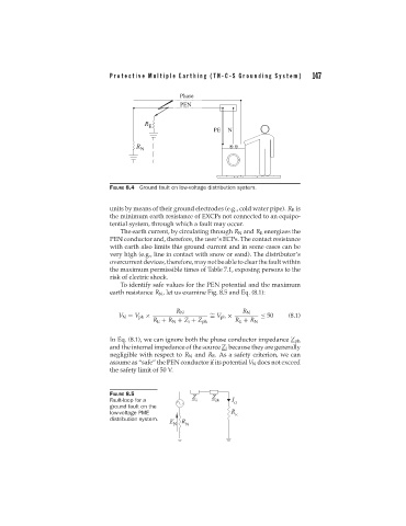
FIGURE 8.4 Ground fault on low-voltage distribution system.
units by means of their ground electrodes (e.g., cold water pipe). R E is
the minimum earth resistance of EXCPs not connected to an equipo-
tential system, through which a fault may occur.
The earth current, by circulating through R N and R E energizes the
PEN conductor and, therefore, the user’s ECPs. The contact resistance
with earth also limits this ground current and in some cases can be
very high (e.g., line in contact with snow or sand). The distributor’s
overcurrent devices, therefore, may not be able to clear the fault within
the maximum permissible times of Table 7.1, exposing persons to the
risk of electric shock.
To identify safe values for the PEN potential and the maximum
earth resistance R N , let us examine Fig. 8.5 and Eq. (8.1):
R N R N
V N = V ph × ∼ ≤ 50 (8.1)
= V ph ×
R E + R N + Z i + Z ph R E + R N
In Eq. (8.1), we can ignore both the phase conductor impedance Z ph
and the internal impedance of the source Z i because they are generally
negligible with respect to R N and R E . As a safety criterion, we can
assume as “safe” the PEN conductor if its potential V N does not exceed
the safety limit of 50 V.
FIGURE 8.5
Fault-loop for a
ground fault on the
low-voltage PME
distribution system.