
Page 162 - Electrical Safety of Low Voltage Systems
P. 162
Protective Multiple Earthing (TN-C-S Grounding System) 145
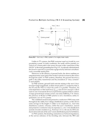
FIGURE 8.3 Fault-loop in PME systems for single-phase loads.
Unlike in TT systems, the PME customer need not install its own
grounding system. In fault conditions, the earth will be partially in-
volved as a return path to the source because of the connection of the
1
EXCPs to the main grounding bus (Fig. 8.3). As already substantiated,
this bond is essential to guarantee equipontiality between simultane-
ously accessible metal parts.
Moreover, in the absence of ground faults, the above earthing ar-
rangement may cause part of the neutral current to return to the source
through the earth. In PME systems, therefore, the ground becomes a
path to the utility transformer and the circulation of “stray currents”
is unavoidable.
In PME systems, ground-fault currents arising at the user’s loca-
tion have large magnitude, as their return path is a conductor, that is,
the PE and the PEN to which the earth is in parallel. Therefore, the
total impedance of the fault-loop |Z Loop | may be low enough to allow
users to use overcurrent devices as protection against indirect contact.
A large ground-fault current, in fact, can easily fulfill Eq. (7.4). Hence,
the presence of RCDs in PME systems is not a mandatory safety re-
quirement, as is in TT systems.
The combined neutral and protective conductors (PEN) may exist
throughout the utility low-voltage distribution system, as this allows
some savings in the length of cables to be employed (i.e., four-wire
distribution system), whereas, within the user’s installation, neutral
and protective conductors may be separate (i.e., five-wire distribution
system).Insomecountries(e.g.,Norway,U.S.A.),theuseofaPENcon-
ductor downstream of the user’s main distribution panel is forbidden.
In PME systems, the bonding connection is of utmost importance,
at the service entrance of the dwelling unit, between the PEN and