
Page 167 - Electrical Safety of Low Voltage Systems
P. 167
150 Chapter Eight
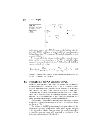
FIGURE 8.9
Equivalent fault-loop
for a short circuit
phase-to-PEN
in PME.
equipotential reasons to the PEN. Such current, in fact, is greatly lim-
ited by the EXCPs’ resistance-to-ground, which is much larger than
the impedance of the PEN conductor. The equivalent fault-loop circuit
is shown in Fig. 8.9.
By assuming both the internal resistance of the source to be neg-
ligible and the cross-sectional area of the PEN as half of the phase
conductor (common situation), the user’s ECPs will reach the follow-
ing prospective touch voltage:
Z PEN 2Z ph 2
V ST = V ph × = V ph × = × V ph (8.3)
Z + Z 2Z + Z 3
PEN ph ph ph
Users are exposed to this voltage for the time the distributor’s protec-
tive device takes to clear the fault.
8.3 Interruption of the PEN Conductor in PME
As already substantiated in Sec. 7.8 for TN systems, the accidental in-
terruption of the PEN conductor causes all the ECPs supplied down-
stream of the interruption to be energized at the line-to-line potential,
even if healthy. PME have a much larger geographical extension than
TN systems and therefore the risk of the interruption of the PEN con-
ductor and of the energization of the ECPs of more than one customer
is higher. Hence, the installation of the PEN conductor should be in
such a way as to minimize the probability of its break.
ThelossofthePENconductoralsotriggersovervoltages.Letusex-
amine Fig. 8.10, where two users are supplied by two different phases
and the same PEN.
The absence of the PEN as a return path causes a voltage divider
between the two users’ single-phase loads, which are now supplied
by the line-to-line voltage. This may cause the supply to each load
to exceed the nominal value, with great risk of overheating of the
equipment and therefore of initiating fire.