
Page 324 - Electrical Properties of Materials
P. 324
306 Lasers
(a) Absorption
(b)
b
S
1
Fluorescence
B
Absorption
Energy Excitation Emission Absorption Relative intensity
Tuning
range
560 580 600 620
a
S 0 Wavelength (nm)
A
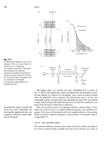
Fig. 12.7
(a) The relevant energy levels of a dye
molecule. The wavy arrows from b to
B and from a to A represent (c)
Dielectric
non-radiative transitions. The broken Diffraction
mirror Flashlamp
lines leading to the right also grating
represent non-radiative transitions in Laser
which some other states are involved. output
Dye cuvette
(b) The tuning range of rhodamine 6G
as a function of wavelength. Rotation
Dye Dye
(c) Schematic representation of a for
out in
tuneable dye laser. tuning
The tuning range of a specific dye laser (rhodamine 6G) is shown in
Fig. 12.7(b) by the shaded area, where the fluorescent and absorption curves
are also plotted as a function of wavelength. Laser action becomes possible
when the absorption curve intersects the fluorescence curve. At the long
wavelength extreme, the gain of the laser (meaning the gain of the wave during
a single transit between the reflectors) becomes too small for oscillation, as a
result of the decrease in fluorescence efficiency.
Note that this range is not the end How can we tune the laser? An ingenious solution is shown in Fig. 12.7(c),
of the dye laser’s tuneability. By where one of the mirrors is a rotatable diffraction grating. The oscillation fre-
choosing the appropriate dyes any quency of the laser will be determined by the angular position of the grating,
frequency within the visible range which will reflect a different frequency at each position. The tuneable range is
may be obtained. a respectable 7%.
12.6.4 Gas-dynamic lasers
The essential difference between these lasers and all the others discussed so
far is that no electric input is needed. One starts with a hot gas (e.g. CO 2 )in