
Page 328 - Electrical Properties of Materials
P. 328
310 Lasers
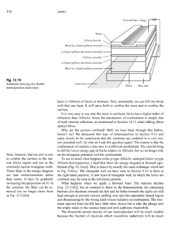
Forward-bias voltage
Metal
Silicon dioxide
Heavily p-doped gallium arsenide
p-Doped gallium aluminium arsenide
Gallium arsenide
n-Doped gallium aluminium arsenide
Heavily n-doped gallium arsenide
Fig. 12.10
Schematic drawing of a double Laser beam
Metal Heat sink
heterojunction diode laser.
layer (≈100 nm) of GaAs in between. Very remarkably, we can kill two birds
with that one layer. It will serve both to confine the wave and to confine the
carriers.
It is very easy to see why the wave is confined. GaAs has a higher index of
refraction than AlGaAs, hence the mechanism of confinement is simply that
of total internal reflection, as mentioned in Section 10.15 when talking about
optical fibres.
Why are the carriers confined? Well, we have been through this before,
haven’t we? We discussed this type of heterojunction in Section 9.15 and
came clearly to the conclusion that the electrons are confined to a very nar-
row potential well. So why do I ask this question again? The reason is that the
confinement of carriers is due now to a different mechanism. The crucial thing
is still the lower energy gap of GaAs relative to AlGaAs, but we no longer rely
Note, however, that our aim is now on the triangular potential well for confinement.
to confine the carriers to the nar- To see in detail what happens in the p-type AlGaAs–undoped GaAs–n-type
row GaAs region and not to the AlGaAs heterojunction, I shall first show the energy diagram at thermal equi-
extremely narrow triangular wells. librium [Fig. 12.11(a)]. This is drawn by exactly the same technique which led
These blips in the energy diagram to Fig. 9.41(c). The triangular well we have seen in Section 9.15 is there at
are now embarrassments rather the right-hand junction. A new kind of triangular well, in which the holes are
than assets. In fact, by gradually confined, may be seen at the left-hand junction.
increasing the proportion of A1 in What happens when we apply a forward bias? The barriers decline
the junction, the blips can be re- [Fig. 12.11(b)], but in contrast to those in the homojunction, the remaining
moved (we no longer show them barriers (for electrons towards the left and for holes towards the right) are still
in Fig. 12.11(b)). high enough to prevent carriers spilling over into the oppositely doped region
and disappearing by the wrong kind of non-radiative recombination. The elec-
trons injected from the left have little other choice but to take the plunge into
the empty states in the valence band and emit a photon, meanwhile.
The threshold current density of our heterojunction will be much smaller
because the fraction of electrons which recombine radiatively will be much