
Page 388 - Electrical Properties of Materials
P. 388
370 Optoelectronics
2
514.5 nm, by two beams incident from air at angles ±5 in – XY = r XYZ E Z .
◦
r
the geometry of Fig. 13.3.
(i) Find the dielectric tensor in the presence of an electric
(i) What is the grating spacing in the material? field applied in the Z-direction.
(ii) What should be the incident angle if the hologram is to (ii) Transform this dielectric tensor into the xyz coordinate
be replayed at 633 nm? system. Note that x, y is 45 clockwise from XY.
◦
(iii) If the hologram is to be replayed at the second Bragg (iii) Will the input wave, shown in Fig. 13.28, be affected by
angle, what will that angle be at the two above mentioned the applied electric field?
wavelengths?
(Note: This is the actual tensor of a Bi 12 SiO 20 crystal cut
13.5. A volume hologram is recorded by two beams incident in a certain way, apart from optical activity which we have
perpendicularly upon a photosensitive medium from opposite disregarded here.)
sides (the so-called reflection geometry).
13.7. The differential equations for the amplitudes of waves
(i) What will be the grating spacing at wavelengths 514.5 nm in two coupled waveguides are given in eqns (13.16) and
and 633 nm? Take n = 1.52. (13.17).
(ii) Which configuration do you think will be more sensit- (i) Find the solution with boundary conditions A 1 = A 10 and
ive to replay wavelength, the transmission type or the A 2 =0 at z =0.
reflection type?
(ii) Show that the solution reduces to those of eqns (13.18)
and (13.19) when k 1 = k 2 = k.
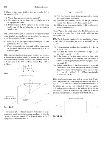
13.6. Some crystals have the property that they are isotropic
(iii) If the length of the interaction region is 1 cm, what
in the absence of an electric field but become aniostropic when
should be the value of the coupling constant in order to
an electric field is applied. The dielectric constant tensor in
achieve complete power transfer from waveguide 1 into
such a material in the XYZ coordinate system (Fig. 13.32) is
waveguide 2?
as follows:
XX 0 0
⎡ ⎤ (iv) By how much should v 2 the phase velocity in waveguide
⎣ 0 YY 0 ⎦ , 2 be different from that in waveguide 1 in order to reduce
= 0
0 0 ZZ the power coupled into waveguide 2 by a factor 2? Take
–1
L =1 cm, K = π/2cm , λ = 633 nm, and, initially,
where 8 –1
v 1 = v 2 = v =10 ms .
r = XX = YY = ZZ .
13.8. An electromagnetic wave with an electric field E i is in-
y
X cident perpendicularly on the Fabry–Perot resonator shown in
Fig. 13.33. The amplitude reflectivities and transmittivities of
Y x
the mirrors are r 1 , t 1 and r 2 , t 2 respectively, the wave number
is k, and the gain coefficient of the medium filling the res-
onator is γ . Derive an expression (by summing an infinite
geometrical series) for the transmitted electric field, E t .
Z,z
Electric field
polarized vertically Fabry–Perot resonator
incident
beam
i t
Fig. 13.32
The electro-optic coefficient may now be assumed to have a
component which relates, in the same coordinate system, the
change in the XY component of the dielectric tensor to the Z, Fig. 13.33
component of the electric field as