
Page 439 - Electrical Properties of Materials
P. 439
The ‘perfect’ lens 421
ε = –1 ε = –1 ε = –1
τ
τ
τ
μ τ = –1 μ τ = –1 μ τ = –1
Fig. 15.17
d 3d 5d 7d 9d 11d Schematic representation of a
z = 0 6d
2 2 2 2 2 2 multilayer lens.
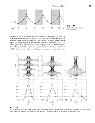
Gaussian of 14 nm half-width, and the wavelength of operation is 365 nm. The
total width of the structure is 80 nm. In the three cases investigated there are
first four 10 nm layers, secondly two 20 nm layers, and finally a single 40 nm
layer. The imaginary part of the dielectric constant is taken as ε =0.1. The
r
upper figures show the streamlines of the Poynting vector, and the lower figures
the relative values of the object and image distributions. It may be clearly seen
that for the same total width, the multilayer lens produces a much better image.
80 80 80
60 60 60
z [nm] 40 40 40
20 20 20
0 0 0
–40 0 40 –40 0 40 –40 0 40
x [nm] x [nm] x [nm]
1 1 1
0.8 0.8 0.8
0.6 0.6 0.6
0.4 0.4 0.4
0.2 0.2 0.2
0 0 0
–40 –20 0 20 40 –40 –20 0 20 40 –40 –20 0 20 40
x [nm] x [nm] x [nm]
(a) (a)
Fig. 15.18
A lens of 80 nm overall thickness. Upper figure: Poynting vector streamlines. Lower figure: object and image. The object in all
three cases is a Gaussian. The lens consists of (a) four 10 nm layers, (b) two 20 nm layers, (c) one 40 nm layer.