
Page 101 - Embedded Microprocessor Systems Real World Design
P. 101
WATCHDOG TIMER
WRITE STROBE FROM MICROPROCESSOR 7 RESET TO MICROPROCESSOR
f-7
07-9
TRIG
WRITE STROBE FROM MICROPROCESSOR I I I I I I I
I
ONESHOT OUTPUT k7-q 1
I
I
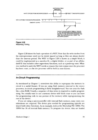
THIS IS THE WATCHDOG TIMEOUT PERIOD.
IF ME TIME BETWEEN MICROPROCESSOR
WRITES TO THE WATCHDOG EXCEEDS THIS
TIME, THE WATCHDOG WILL RESET THE
MICROPROCESSOR.
Figure 2.26
Watchdog Timing.
Figure 2.26 shows the basic operation of a WDT. Note that the write strobes from
the microprocessor need not be evenly spaced as long as they are always shorter
than the timeout period. The WDT in Figure 2.26 is shown as a simple block; it
could be implemented as a one-shot IC, a digital divider, or as part of an off-the-
shelf IC that includes other supervisory functions, such as a power-up reset. What-
ever method is used, the WDT needs to remove the reset output once the processor
has been reset, or else the processor will be held in reset forever.
In-Circuit Programming
As mentioned in Chapter 1, sometimes the ability to reprogram the memory in-
circuit is a useful feature. If you are using flash memory external to the micro-
processor, incircuit programming is fairly straightforward. You can treat the flash
like a slow RAM. Usually, a sequence of data writes is required to enable program-
ming. You usually want to use a memory device with block erase so you can leave
the programming code in one portion of the memory while reprogramming the
rest of the device.
If you are using a microcontroller with internal flash memory, some extra con-
siderations are required. The device pins needed for programming typically are
shared with other functions. As an example, look at the Microchip PIC 16F84. The
16F84 has 1K of internal flash memory. To program the device, data are loaded
Hardware Design I 83