
Page 102 - Embedded Microprocessor Systems Real World Design
P. 102
and read serially using two of the port pins, RB6 and RB7. The MCLR pin is used
to provide the +12V programming voltage.
The problem with this approach is that the 16F84 has only 18 pins; in many
designs you would need -6 and RB7 for some other function. Thus, you must
make these pins do double duty, functioning as normal 1/0 pins and also as in-
circuit programming pins. This is complicated by the fact that RB7 is bidirectional
in programming mode.
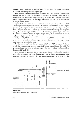
Figure 2.27 shows one way to implement incircuit programming with the 16F84.
The two programming pins are driven with open-collector buffers. When not prc-
gramming, the inputs to the opencollector buffers are high, making the outputs
float. The pins then can be driven by (or drive) external circuitry. For program-
ming, the external logic must be turned off and the programming buffers drive
the pins. The external device doing the programming must have separate data-in
and data-out pins to make this work.
In Figure 2.27, RB6 is an input in normal operation; RB7 is an output. Of course,
you must be sure that the external logic does not get confused when programming
data is applied to the device pins.
An alternative way to do this is to connect RB6 and RB7 through a PLD and
switch the programming function on and off with a control input. The +12V for
programming comes from an external supply that can be switched off or switched
between +12V and +5V.
This example is specific to the PIC processors, but you find similar situations
with other processors that have flash memory and in-circuit programming capa-
bility. For example, the NEC pPD78F9026A processor allows you to use either the
*5v
WLLUP RESISTORS
+J OPEN CMLECTOR
WLLUP RESISTORS
KfEP INRlTS HIGH
WWEW MI CONNECTED
moow.uu CLOCK
Figure 2.27
In-Circuit Programming of a PIC16F84.
84 Embedded Mieropocessm Systems