
Page 239 - Embedded Microprocessor Systems Real World Design
P. 239
CAN error checking is performed by three methods:
The CRC (a complex checksum method) is calculated and inserted into the
message by the transmitter. The receiving node calculates the same CRC and
compares it against the received CRC to detect transmission errors. If a CRC
error is detected, an error frame is generated to request retransmission.
The second error check uses the acknowledge bit; the message is sent from the
transmitter to the receiver, but the acknowledge bit is sent from the receiver to
the transmitter. If no acknowledge bit is received, the message is retransmitted.
Finally, a frame check is performed by the transmitter, in which it looks for an
incorrect state during the CRC delimiter, acknowledge delimiter, end-of-frame
and interframe space periods. An incorrect signaling value during these periods
is an error.
There are two versions of CAN: Version 2.0A (Standard CAN) supports an
11-bit identifier field (supports 2047 message types) and version 2.OB (Extended
CAN) supports an 18-bit identifier extension, for a total 29-bit identifier field.
CAN interconnects can be up to 40m long at 1 Mbps. Longer cables can be used
with lower bit rates. Up to 30 nodes may be connected to a single CAN bus. A
number of manufacturers make microcontrollers that interface directly to CAN
bus. Examples are the Siemens C167R and Intel 87C196CB. Intel also makes a com-
munications controller, the 82527, that provides a CAN interface for processors that
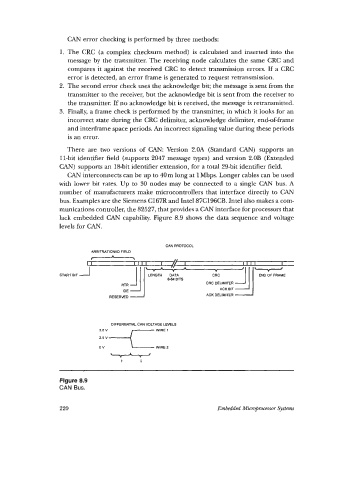
lack embedded CAN capability. Figure 8.9 shows the data sequence and voltage
levels for CAN.
CAN PROTOCOL
ARBlTRATlONtlD FIELD
-
DIFFERENTIAL CAN VOLTAGE LEVELS
:::L(-'
WIRE 1
ov WIRE 2
I 0
Figure 8.9
CAN Bus.
220 Embedded Micr@-rocessm Systems