
Page 80 - Academic Press Encyclopedia of Physical Science and Technology 3rd BioTechnology
P. 80
P1: GRB Final Pages
Encyclopedia of Physical Science and Technology EN002G-67 May 25, 2001 20:8
262 Bioreactors
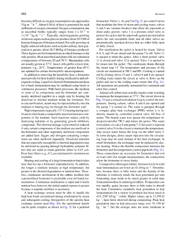
becomes difficult as oxygen consumption rate approaches bioreactor. Valves 1, 10, and 5 in Fig. 21 are control valves
−1
5kgm −3 h . About 0.54 kJ of heat is generated for each that modulate the flow of steam and cooling water; valves
millimole of oxygen consumed. Oxygen consumption rate 2 and 9 are vacuum breakers that allow the pipework to
in microbial broths typically ranges from 2 × 10 −4 to drain under gravity; valve 3 is a pressure relief valve to
−1
1×10 −3 kg m −3 s . Typically, microorganisms growing protect the jacket and the pipework against pressurization
onhexosesugarssuchasglucoseproduceabout10.9MJof above the safe acceptable limit; and all other valves are
heat per kilogram of biomass formed. For cells growing on pneumatically operated devices that are either fully open
highly reduced substrates such as hydrocarbons, heat gen- or fully closed.
eration is greater, about 28.5 MJ/kg of biomass produced. For sterilization the jacket is heated by steam. Valves
These figures are for fermentations in which biomass is the 4–6, 8, and 10 are closed and the pump 7 is off. Valve 11
onlyproduct.Mostmicrobialandplantcellsareculturedat is opened to drain the jacket. After a short period, valve
◦
a temperature of between 20 and 30 C. Mammalian cells 11 is closed and valve 12 is opened. Valve 1 is opened to
◦
are usually grown at 37 C. Insect cells prefer a lower tem- let steam into the jacket. The condensate drains through
◦
◦
perature, e.g., 26 C. Temperatures of greater than 40 C the steam trap 13. The temperature and pressure of the
are optimal for certain thermophilic microorganisms. circuit are monitored at TIC1 and PI1. Cooling is carried
In addition to removing the metabolic heat, a fermenter out by closing valves 12 and 1; valves 8 and 4 are opened.
must provide for heat transfer during sterilization and sub- Cooling water enters the circuit at valve 4, flowsupthe
sequentcooling.Liquid(orslurried)fermentationmedium jacket and out to the cooling water return line (Fig. 21).
for a batch fermentation may be sterilized using batch or All operations are generally automated for consistent and
continuous processes. With batch processes, the medium error-free control.
or some of its components and the fermenter are com- Animal cell culture may actually require some warming
◦
monly sterilized together in a single step by heating the to maintain the temperature at 37 C. The circuit shown in
dissolved or slurried medium inside the fermenter. For Fig. 21 uses a closed recirculation loop to control the tem-
in situ sterilization, steam may be injected directly into the perature. During culture, valves 8 and 6 are opened and
medium or heating may be through the fermenter wall. the pump 7 is turned on. The water is pumped through
High temperature (typically 121 C) heating during ster- a compact plate heat exchanger (PHE) where it is in-
◦
ilizationoftenleadstoundesirablereactionsbetweencom- directly heated by controlled (control valve 10) flow of
ponents of the medium. Such reactions reduce yield by steam. The heated water now passes the temperature in-
destroying nutrients or by generating growth inhibitory dicator/controller TIC1 and enters the jacket. The water
compounds. This thermal damage is prevented or reduced recirculates via valve 8 and pump 7. Cold water is injected
if only certain components of the medium are sterilized in (control valve 5) in the circuit to maintain the temperature.
the fermenter and other separately sterilized components Any excess water leaves the loop via the relief valve 3.
are added later. Sugars and nitrogen-containing compo- In some designs, direct steam injection into the circulat-
nents are often sterilized separately. Dissolved nutrients ing loop may be used instead of the heat exchanger. In
that are especially susceptible to thermal degradation may small fermenters, the exchanger may be replaced by elec-
be sterilized by passing through hydrophilic polymer fil- tric heating. Notice the flexible connections between the
ters that are rated to retain particles down to 0.45 µm. fermenter and the temperature control pipework (Fig. 21).
Even finer filters (e.g., 0.2 µm rated particle retention) are These connections are necessary for fermenters that rest
available. on load cells (for weight measurement); the connections
Heating and cooling of a large fermentation batch takes allow the fermenter to move freely.
time that ties up a fermenter unproductively. In addition, Compared to submerged culture, biomass levels in solid
−3
the longer a medium remains at high temperature, the state fermentations are lower at 10–30 kg m . Neverthe-
greater is the thermal degradation or nutrient loss. There- less, because there is little water and the density of the
fore, continuous sterilization of the culture medium into substrate is relatively small, the heat generation per unit
a presterilized fermenter is preferable even for batch fer- fermenting mass tends to be much greater in solid state
mentations. Continuous sterilization is rapid and it limits fermentations than in submerged culture. Temperature can
nutrient loss; however, the initial capital expense is greater rise rapidly, again, because there is little water to absorb
because a separate sterilizer is necessary. the heat. Cumulative metabolic heat generation in koji
A heat exchange system must be able to handle the fermentations for a variety of products has been noted at
high heat loads encountered during sterilization by steam 419–2387 kJ kg −1 solids. Higher values, up to 13,398 kJ
−1
and subsequent cooling. Irrespective of the specific heat kg , have been observed during composting. Peak heat
exchange system used (Fig. 20), the operational details generation rates in koji processes range over 71–159 kJ
−1
can be quite complex as shown in Fig. 21 for a jacketed kg −1 hr , but the average rates are more moderate at