
Page 77 - Academic Press Encyclopedia of Physical Science and Technology 3rd BioTechnology
P. 77
P1: GRB Final Pages
Encyclopedia of Physical Science and Technology EN002G-67 May 25, 2001 20:8
Bioreactors 259
bearings inside the vessel. The shaft of the agitator is pro-
vided with steam sterilizable single or double mechanical
seals. Double seals are preferred, but they require lubrica-
tion with cooled clean steam condensate, or other sterile
fluid. Alternatively, when torque limitations allow, mag-
netically coupled agitators may be used thereby eliminat-
ing the mechanical seals.
An air (or other gas mixture) sparger supplies oxygen
(and sometimes carbon dioxide or ammonia for pH con-
trol) to the culture. Aeration of fermentation broth gen-
erates foam. Typically, 20 to 30% of the fermenter vol-
ume must be left empty to accommodate the foam and
allow for gas disengagement. Foaming in bioreactors is
controlled by a combination of chemical and mechani-
cal methods. Chemical antifoaming agents are commonly
mixed with the broth at initiation of fermentation. Fur-
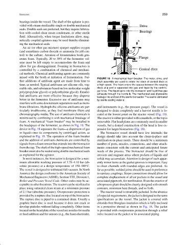
FIGURE 19 A mechanical foam breaker. The motor, drive, and
ther additions of antifoam agent are made from time to shaft assembly are used to rotate the stack of conical discs at
time, as needed. Typical antifoams are silicone oils, veg- a high speed. The foam enters the spaces between the rotating
etable oils, and substances based on low molecular weight discs at a and is separated into gas and liquid by the centrifu-
gal force. The liquid spins into the bioreactor and liquid-free gas
poly(propylene glycol) or poly(ethylene glycol). Emulsi-
exhausts through the nozzle b. The mechanical seal d prevents
fied antifoams are more effective because they disperse leakage into and out of the sterile bioreactor. The seal is lubricated
better in the fermenter. Excessive use of antifoams may by sterile cooling water c.
interfere with some downstream separations such as mem-
brane filtrations. Hydrophobic silicone antifoams are par- and instruments (e.g., the pressure gauge). The vessel is
ticularly troublesome, as they foul membrane filters and designed to drain completely and a harvest nozzle is lo-
chromatography media. The use of antifoam chemicals is cated at the lowest point on the reactor vessel (Fig. 18).
minimized by combining it with mechanical breakage of The reactor is either provided with a manhole, or the top is
foam. A mechanical “foam breaker” may be installed in removable. Flat head plates are commonly used in smaller
the headspace of the fermenter, as shown in Fig. 18. The vessels, but a domed construction of the head is less ex-
device in Fig. 18 separates the foam—a dispersion of gas pensive for larger bioreactors (Fig. 18).
in liquid—into its components by centrifugal action, as The bioreactor vessel should have few internals; the
explained in Fig. 19. The operation of the foam breaker design should take into account the clean-in-place and
and the addition of antifoam chemicals are controlled by sterilization-in-place needs. There should be a minimum
signals from a foam sensor that extends into the bioreactor number of ports, nozzles, connections, and other attach-
from the top. The shaft of the high-speed mechanical foam ments consistent with the current and anticipated future
breaker must also be sealed using double mechanical seals needs of the process. The bioreactor should be free of
as explained for the agitator. crevices and stagnant areas where pockets of liquids and
In most instances, the bioreactor is designed for a max- solids may accumulate. Attention to design of such appar-
imum allowable working pressure of 3.78–4.10 bar (ab- ently minor items as the gasket grooves is important. Easy
solute pressure) at a design temperature of 150–180 C. to clean channels with rounded edges are preferred. As
◦
The vessel is designed to withstand full vacuum. In North far as possible, welded joints should be used in preference
America the design conforms to the American Society of to sanitary couplings. Steam connections should allow for
Mechanical Engineers (ASME), Section VIII, Division 1, complete displacement of all air pockets in the vessel and
Boiler and Pressure Vessel Code. Other codes may be ac- associated pipework, for sterilization. Evan the exterior of
ceptable in other locations. The reactor can be sterilized in a bioprocess plant should be cleanly designed with smooth
place using saturated clean steam at a minimum pressure contours, minimum bare threads, and so forth.
of 2.1 bar (absolute pressure). Overpressure protection is The reactor vessel is invariably jacketed. In the absence
provided by a rupture disc located on top of the bioreactor. of especial requirements, the jacket is designed to the same
The rupture disc is piped to a contained drain. Usually a specifications as the vessel. The jacket is covered with
graphite burst disc is used because it does not crack or chloride-free fiberglass insulation which is fully enclosed
develop pinholes without failing completely. Other items in a protective shroud as shown in Fig. 18. The jacket
locatedontheheadplateofthevesselarenozzlesformedia is provided with overpressure protection through a relief
or feed addition and for sensors (e.g., the foam electrode), valve located on the jacket or its associated piping.