
Page 175 - Academic Press Encyclopedia of Physical Science and Technology 3rd Chemical Engineering
P. 175
P1: GGY Final Pages
Encyclopedia of Physical Science and Technology EN004D-156 June 8, 2001 15:28
18 Cryogenic Process Engineering
ways. If a low-temperature liquid is formed in the pro-
cess, the heat that is absorbed evaporates the liquid, and
refrigeration is accomplished at constant temperature. If
the refrigerator is designed to reduce the process fluid to a
cold gaseous state, the heat absorbed changes the sensible
heat and consequently the temperature of the fluid.
In a continuous refrigeration process, there is no ac-
cumulation of refrigerant in any part of the system. This
contrasts with a gas-liquefying system, where liquid ac-
cumulates and is withdrawn. Thus, in a liquefying system,
the total mass of gas that is warmed and returned to the
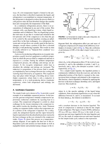
low-pressure side of the compressor is less than the gas FIGURE 2 (a) Schematic for simple Linde-cycle refrigerator; (b)
to be cooled by the amount liquefied, creating an unbal- temperature–entropy diagram for cycle.
anced flow in the heat exchangers. In a refrigerator, the
warm and cool gas flows are usually equal in the heat ex- frigerant fluid, the refrigeration effect per unit mass of
changers, except where a portion of the flow is diverted refrigerant compressed will simply be the difference in en-
through a work-producing expander. This results in what thalpies of streams 1 and 2 of Fig. 2a. Thus, the coefficient
is usually referred to as “balanced flow condition” in a of performance (COP) of the ideal simple Linde cycle is
heat exchanger. given by:
A process for producing refrigeration at cryogenic tem-
peratures usually involves equipment at ambient temper- Q ref h 1 − h 2
COP = = (1)
ature in which the process fluid is compressed and heat is W T 1 (s 1 − s 2 ) − (h 1 − h 2 )
rejected to a coolant. During the ambient temperature
where Q ref is the refrigeration effect; W the work of com-
compression process, the enthalpy and entropy are de-
pression; h 1 and h 2 the enthalpies at points 1 and 2, re-
creased. At the cryogenic temperature where heat is
spectively; and s 1 and s 2 the entropies at points 1 and 2,
absorbed, the enthalpy and entropy are increased. The
respectively, of Fig. 2a.
reduction in temperature of the process fluid is usually
For a simple Linde liquefier, the liquefied portion is
accomplished by heat exchange between the cooling and
continuously withdrawn from the reservoir, and only the
warming fluid followed by an expansion. This expansion
unliquefied portion of the fluid is warmed in the coun-
may take place either through a throttling device (isen-
tercurrent heat exchanger and returned to the compressor.
thalpic expansion), where there is only a reduction in
The fraction y that is liquefied is obtained by applying the
temperature, or in a work-producing device (isentropic
first law to the heat exchanger, throttling valve, and liquid
expansion), where both temperature and enthalpy are
reservoir. This results in:
decreased.
y = (h 1 − h 2 )/(h 1 − h f ) (2)
A. Isenthalpic Expansion
where h f is the specific enthalpy of the liquid being
The simple Linde cycle shown in Fig. 2a provides a good withdrawn. Note maximum liquefaction occurs when the
example of an isenthalpic expansion process. In this pro- difference between h 1 and h 2 is maximized. To account
cess the gaseous refrigerant is initially compressed to ap- for heat inleak q L , the relation is modified to:
proximate isothermal conditions by rejecting heat to a
coolant. The compressed refrigerant is cooled in a heat y = (h 1 − h 2 − q L )/(h 1 − h f ) (3)
exchanger by the stream returning to the compressor in-
with a resultant decrease in the fraction liquefied. The
take until it reaches the throttling valve. Joule–Thomson
work of compression is identical to that for the simple
cooling on expansion further reduces the temperature un-
Linde refrigerator. The figure of merit (FOM), defined as
til a portion of the refrigerant is liquefied. For a refrig-
(W/m f ) i /(W/m f ), where (W/m f ) i is the work of com-
erator, the unliquefied fraction and the vapor formed by
pression per unit mass liquefied for the ideal liquefier and
liquidevaporationfromtheabsorbedheat Q arewarmedin
(W/m f ) the work of compression per unit mass liquefied
the heat exchanger as they are returned to the compressor
for the simple Linde cycle, reduces to the expression:
intake. Figure 2b shows this process on a temperature–
entropy diagram. If one applies the first law to this re-
T 1 (s 1 − s f ) − (h 1 − h f ) h 1 − h 2
frigeration cycle and assumes no heat inleaks as well as FOM = (4)
negligible kinetic and potential energy changes in the re- T 1 (s 1 − s 2 ) − (h 1 − h 2 ) h 1 − h f