
Page 180 - Academic Press Encyclopedia of Physical Science and Technology 3rd Chemical Engineering
P. 180
P1: GGY Final Pages
Encyclopedia of Physical Science and Technology EN004D-156 June 8, 2001 15:28
Cryogenic Process Engineering 23
pure nitrogen at the top (provided that argon and the rare B. Rare Gas Recovery
gases have been previously removed). More than enough
liquid nitrogen is produced in the lower column, so that Argon,neon,krypton,andxenonarerecoveredasproducts
some may be withdrawn and introduced in the upper col- in commercial air separation plants. Since atmospheric air
umn as needed reflux. Since the condenser must condense contains 0.93% argon with a boiling point intermediate
nitrogen vapor in the lower column by evaporating liq- between those of nitrogen and oxygen, the argon will ap-
uid oxygen in the upper column, it is necessary to op- pear as an impurity in either or both the nitrogen and the
erate the lower column at a higher pressure, ∼0.5 MPa, oxygen product of an air separation plant. Thus, removal
while the upper column is operated at ∼0.1 MPa. This of the argon is necessary if pure oxygen and nitrogen are
requires throttling to reduce the pressure of the fluids desired from the air separation.
from the lower column as they are transferred to the upper Figure 10 illustrates the scheme for removing and
column. concentrating the argon. The upper column is tapped at
The processes used in industrial air-separation plants the level where the argon concentration is highest in the
have changed very little in basic principle during the past column. Gas rich in argon is fed to an auxiliary column,
25 years. After cooling the compressed air to its dew point where the argon is separated, and the remaining oxygen
in a main heat exchanger by flowing counter current to the and nitrogen mixture is returned to the appropriate level
products of separation, the air feed, at an absolute pres- in the primary column. The yield for this type of plant
sure of about 6 MPa, is separated in a double distillation is about 50% of the atmospheric argon. The crude argon
column. This unit is kept cold by refrigeration developed product generally contains 45% argon, 50% oxygen, and
in a turbine, which expands a flow equivalent to between 5% nitrogen. The oxygen is readily removed by chemical
8 and 15% of the air-feed stream down to approximately reduction or adsorption. The remaining nitrogen impurity
atmospheric pressure. is of no consequence if the argon is to be used for filling
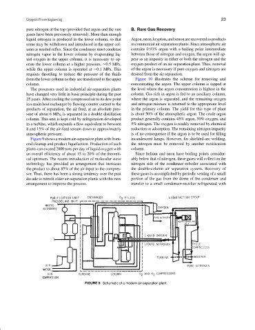
Figure9showsamodernair-separationplantwithfront- incandescent lamps. However, for shielded-arc welding,
end cleanup and product liquefaction. Production of such the nitrogen must be removed by another rectification
plants can exceed 2800 tons per day of liquid oxygen with column.
an overall efficiency of about 15 to 20% of the theoreti- Since helium and neon have boiling points consider-
cal optimum. The recent introduction of molecular sieve ably below that of nitrogen, these gases will collect on the
technology has provided an arrangement that increases nitrogen side of the condenser–reboiler associated with
the product to about 85% of the air input to the compres- the double-column air separation system. Recovery of
sor. Thus, there has been a strong tendency over the past these gases is accomplished by periodic venting of a small
decade to retrofit older air-separation plants with this new portion of the gas from the dome of the condenser and
arrangement to improve the process. transfer to a small condenser–rectifier refrigerated with
FIGURE 9 Schematic of a modern air-separation plant.