
Page 179 - Academic Press Encyclopedia of Physical Science and Technology 3rd Chemical Engineering
P. 179
P1: GGY Final Pages
Encyclopedia of Physical Science and Technology EN004D-156 June 8, 2001 15:28
22 Cryogenic Process Engineering
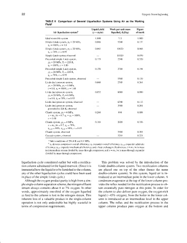
TABLE II Comparison of Several Liquefaction Systems Using Air as the Working
Fluid a
Liquid yield Work per unit mass Figure
Air liquefaction system b (y = ˙ m f / ˙ m) liquefied, (kJ/kg) of merit
Ideal reversible system 1.000 715 1.000
Simple Linde system, p 2 = 20 MPa, 0.086 5240 0.137
η c = 100%, ε = 1.0
Simple Linde system, p 2 = 20 MPa, 0.061 10620 0.068
η c = 70%, ε = 0.95
Simple Linde system observed — 10320 0.070
Precooled simple Linde system, 0.179 2240 0.320
p 2 = 20 MPa, T 3 = 228 K,
η c = 100%, ε = 1.00
Precooled simple Linde system, 0.158 3700 0.194
p 2 = 20 MPa, T 3 = 228 K,
η c = 70%, ε = 0.95
Precooled simple Linde system, observed — 5580 0.129
Linde dual-pressure system, 0.060 2745 0.261
p 3 = 20 MPa, p 2 = 6MPa,
i = 0.8, η c = 100%, ε = 1.00
Linde dual-pressure system, 0.032 8000 0.090
p 3 = 20 MPa, P 2 = 6MPa,
i = 0.8, η c = 70%, ε = 0.95
Linde dual-pressure system, observed — 6340 0.113
Linde dual-pressure system, — 3580 0.201
precooled to 228 K, observed
Claude system, p 2 = 4 MPa, 0.260 890 0.808
x = ˙ m e / ˙ m = 0.7 η c = η e = 100%,
ε = 1.00
Claude system, p 2 = 4 MPa, 0.189 2020 0.356
x = ˙ m e / ˙ m = 0.7, η c = 70%,
η e,ad = 80%, η e,m = 90%, ε = 0.95
Claude system, observed — 3580 0.201
Cascade system, observed — 3255 0.221
a Inlet conditions of 294.4 K and 0.1 MPa.
b η c denotes compressor overall efficiency; η c expander overall efficiency; η e,ad expander adiabatic
efficiency; η e,m expander mechanical efficiency; and ε heat exchanger effectiveness. i = m 1 /m is mass
in intermediate stream divided by mass through compressor, and x = m e /m is mass through expander
divided by mass through compressor.
liquefaction cycle considered earlier but with a rectifica- This problem was solved by the introduction of the
tion column substituted for the liquid reservoir. (Since it is Linde double-column system. Two rectification columns
immaterial how the liquid is to be furnished to the column, are placed one on top of the other (hence the name
any of the other liquefaction cycles could have been used double-column system). In this system, liquid air is in-
in place of the simple Linde cycle.) troduced at an intermediate point in the lower column. A
Although the oxygen product purity is high from a sim- condenser–evaporator at the top of the lower column pro-
ple single-column separation scheme, the nitrogen effluent vides the reflux needed for the rectification process to ob-
stream always contains about 6 to 7% oxygen. In other tain essentially pure nitrogen at this point. In order for
words, approximately one-third of the oxygen liquefied the column to also deliver pure oxygen, the oxygen-rich
as feed to the column is lost in the nitrogen stream. This liquid (∼45% oxygen), from the boiler in the lower col-
inherent loss of a valuable product in the single-column umn is introduced at an intermediate level in the upper
operation is not only undesirable but highly wasteful in column. The reflux and the rectification process in the
terms of compression requirements. upper column produce pure oxygen at the bottom and