
Page 177 - Academic Press Encyclopedia of Physical Science and Technology 3rd Chemical Engineering
P. 177
P1: GGY Final Pages
Encyclopedia of Physical Science and Technology EN004D-156 June 8, 2001 15:28
20 Cryogenic Process Engineering
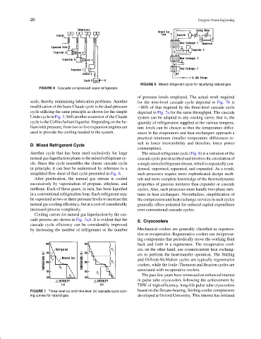
FIGURE 8 Mixed refrigerant cycle for liquefying natural gas.
FIGURE 6 Cascade compressed vapor refrigerator.
of pressure levels employed. The actual work required
seals, thereby minimizing lubrication problems. Another for the nine-level cascade cycle depicted in Fig. 7b is
modification of the basic Claude cycle is the dual-pressure ∼80% of that required by the three-level cascade cycle
cycle utilizing the same principle as shown for the simple depicted in Fig. 7a for the same throughput. The cascade
Linde cycle in Fig. 3. Still another extension of the Claude system can be adapted to any cooling curve; that is, the
cycle is the Collins helium liquefier. Depending on the he- quantity of refrigeration supplied at the various tempera-
lium inlet pressure, from two to five expansion engines are ture levels can be chosen so that the temperature differ-
used to provide the cooling needed in the system. ences in the evaporators and heat exchangers approach a
practical minimum (smaller temperature differences re-
sult in lower irreversibility and therefore lower power
D. Mixed Refrigerant Cycle
consumption).
Another cycle that has been used exclusively for large The mixed refrigerant cycle (Fig. 8) is a variation of the
natural gas liquefaction plants is the mixed refrigerant cy- cascade cycle just described and involves the circulation of
cle. Since this cycle resembles the classic cascade cycle a single mixed refrigerant stream, which is repeatedly con-
in principle, it can best be understood by reference to a densed, vaporized, separated, and expanded. As a result,
simplified flow sheet of that cycle presented in Fig. 6. such processes require more sophisticated design meth-
After purification, the natural gas stream is cooled ods and more complete knowledge of the thermodynamic
successively by vaporization of propane, ethylene, and properties of gaseous mixtures than expander or cascade
methane. Each of these gases, in turn, has been liquefied cycles. Also, such processes must handle two-phase mix-
in a conventional refrigeration loop. Each refrigerant may tures in heat exchangers. Nevertheless, simplification of
be vaporized at two or three pressure levels to increase the the compression and heat exchange services in such cycles
natural gas cooling efficiency, but at a cost of considerably generally offers potential for reduced capital expenditure
increased process complexity. over conventional cascade cycles.
Cooling curves for natural gas liquefaction by the cas-
cade process are shown in Fig. 7a,b. It is evident that the
E. Cryocoolers
cascade cycle efficiency can be considerably improved
by increasing the number of refrigerants or the number Mechanical coolers are generally classified as regenera-
tive or recuperative. Regenerative coolers use reciprocat-
ing components that periodically move the working fluid
back and forth in a regenerator. The recuperative cool-
ers, on the other hand, use countercurrent heat exchang-
ers to perform the heat-transfer operation. The Stirling
and Gifford–McMahon cycles are typically regenerative
coolers, while the Joule–Thomson and Brayton cycles are
associated with recuperative coolers.
The past few years have witnessed an enhanced interest
in pulse tube cryocoolers following the achievement by
TRW of high-efficiency, long-life pulse tube cryocoolers
FIGURE 7 Three-level (a) and nine-level (b) cascade cycle cool- based on the flexure-bearing, Stirling-cooler compressors
ing curves for natural gas. developed at Oxford University. This interest has initiated