
Page 176 - Academic Press Encyclopedia of Physical Science and Technology 3rd Chemical Engineering
P. 176
P1: GGY Final Pages
Encyclopedia of Physical Science and Technology EN004D-156 June 8, 2001 15:28
Cryogenic Process Engineering 19
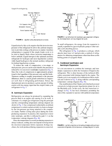
FIGURE 4 (a) Schematic for isentropic gas expansion refrigera-
tor; (b) temperature–entropy diagram for cycle.
FIGURE 3 Liquefier using dual-pressure process.
In small refrigerators, the energy from the expansion is
Liquefaction by this cycle requires that the inversion tem-
usually expended in a gas or hydraulic pump or other suit-
perature of the refrigerant be above the ambient tempera-
able work-absorbing device.
ture to provide cooling as the process is started. Auxiliary
The refrigerator in Fig. 4a produces a cold gas, which
refrigeration is required if the simple Linde cycle is to
absorbs heat from 4–5 and provides a method of refrig-
be used to liquefy fluids whose inversion temperature is
eration for obtaining temperatures other than those at the
below ambient. Liquid nitrogen is the optimum auxiliary
boiling points of cryogenic fluids.
refrigerant for hydrogen and neon liquefaction systems,
while liquid hydrogen is the normal auxiliary refrigerant
for helium liquefaction systems. C. Combined Isenthalpic and
To reduce the work of compression, a two-stage, or Isentropic Expansion
dual-pressure, process can be used whereby the pressure is
It is not uncommon to combine the isentropic and isen-
reduced by two successive isenthalpic expansions (Fig. 3).
thalpic expansions to allow the formation of liquid in the
Since the work of compression is approximately propor-
refrigerator. This is done because of the technical diffi-
tional to the logarithm of the pressure ratio and the Joule–
culties associated with forming liquid in the engine. The
Thomson cooling is roughly proportional to the pressure
Claudecycleisanexampleofacombinationofthesemeth-
difference, there is a much greater reduction in compres-
ods and is shown in Fig. 5a along with the corresponding
sor work than in refrigerating performance. Hence, the
temperature–entropy diagram (Fig. 5b).
dual-pressure process produces a given amount of refrig-
One modification of the Claude cycle that has been used
eration with less energy input than the simple Linde cycle
extensively in high-pressure liquefaction plants for air is
refrigerator in Fig. 2.
the Heylandt cycle. In this cycle, the first warm heat ex-
changer in Fig. 5a has been eliminated, permitting the
B. Isentropic Expansion inlet of the expander to operate with ambient temperature
Refrigeration can always be produced by expanding the
process fluid in an engine and causing it to do work. A
schematic of a simple gas refrigerator using this principle
and the corresponding temperature–entropy diagram are
shown in Fig. 4. Gas compressed isothermally at ambient
temperature is cooled countercurrently in a heat exchanger
by the low-pressure gas being returned to the compres-
sor intake. Further cooling takes place during the work-
producing expansion. In practice, this expansion is never
truly isentropic, and this is reflected by path 3–4onthe
temperature–entropy diagram (Fig. 4b).
Since the temperature in a work-producing expansion is
always reduced, cooling does not depend on being below
the inversion temperature before expansion. In large ma- FIGURE 5 (a) Schematic for combined isenthalpic and isentropic
chines, the work produced during expansion is conserved. expansion refrigerator; (b) temperature–entropy diagram for cycle.