
Page 232 - Academic Press Encyclopedia of Physical Science and Technology 3rd Chemical Engineering
P. 232
P1: GJC Final Pages
Encyclopedia of Physical Science and Technology EN004E-182 June 8, 2001 18:16
556 Distillation
cuts can be taken to obtain lower volatility products. Inter-
mediate cuts of mixed composition are sometimes taken
between each product cut, and these are saved and later
returned to the still pot for inclusion in the next batch.
C. Extractive and Azeotropic Distillation
Conventional distillation tends to be difficult and uneco-
nomical because of the large number of stages required
FIGURE 15 Flash distillation. when the relative volatility between the components to be
separated is very low. In the extreme case, in which an un-
vessel. The temperature and pressure of the liquid entering wanted azeotrope is formed, distillation past the azeotrope
the flash vessel are adjusted to achieve the required degree becomes impossible. Extractive or azeotropic distillation
of vaporization. The compositions of the product streams can sometimes be used to overcome these difficulties.
leaving the flash vessel are different and are a function of Both processes involve the addition of a new material,
the extent to which vaporization occurs. the solvent, to the mixture. The solvent is chosen so as
Although the flash vessel itself is simple, care must be to increase the relative volatility of the components to
taken to ensure that the resultant vapor and liquid phases be separated. During extractive distillation, the solvent is
are separated completely from one another. To this end, generally added near the top of the column, and because
the entering feed is often introduced tangentially rather it has a low volatility it is withdrawn with the product at
than at a 90-degree angle to the vessel wall. An annu- the bottom. In azeotropic distillation, the solvent is with-
lar baffle directs the liquid droplets that are created by drawn as an azeotrope with one or more of the components
the flash toward the bottom of the vessel. By installing a to be separated—usually in the overhead product. If the
wire mesh (approximately 75 mm thick) near the top of ratio of the components to be separated is different in the
the vessel, fine liquid drops are prevented from leaving the withdrawn azeotrope from their ratio in the feed to the col-
top of the vessel as entrainment in the high-velocity vapor umn, then at least a partial separation has been achieved.
stream. In both processes it is necessary to separate the solvent
At best, only one theoretical stage is achieved by a flash from the product. This can be accomplished, for exam-
distillation; however, it is used frequently in cryogenic and ple, by distillation, solvent extraction, or even gravity set-
petroleum processing applications, where its simplicity is tling, depending on the characteristics of the components
often attractive for nondemanding separations. Flashing involved.
often occurs in conventional distillation columns as feed
and reflux streams enter. This flashing must be considered
when column entrance devices and distributors are being D. Reactive Distillation
designed. Many distillation columns reside upstream or downstream
of catalytic reactors. Over the last decade, catalysts have
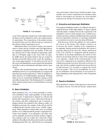
B. Batch Distillation
Batch distillation (Fig. 16) is often preferable to contin-
uous distillation when small quantities of feed material
are processed. A liquid feed is charged to a still pot and
heated until vaporization occurs. Vapor leaves the top of
the column, and after condensation, part is removed as
product and the rest returned to the column as reflux. As
distillation proceeds, the contents of the still pot and the
overhead product become richer in less volatile compo-
nents. When operated at a fixed reflux ratio, an overhead
product cut is collected until the product composition be-
comes unaccceptable. As an alternative, the reflux ratio
can be gradually increased to hold the product composi-
tion constant as the cut is taken. For a fixed rate of heat
addition to the still pot, the latter option results in a steadily
declining product flow rate. After the first cut, subsequent FIGURE 16 Batch distillation.