
Page 283 - Academic Press Encyclopedia of Physical Science and Technology 3rd Chemical Engineering
P. 283
P1: FYK/LPB P2: FPP Final
Encyclopedia of Physical Science and Technology EN006C-252 June 27, 2001 14:15
Fluid Mixing 83
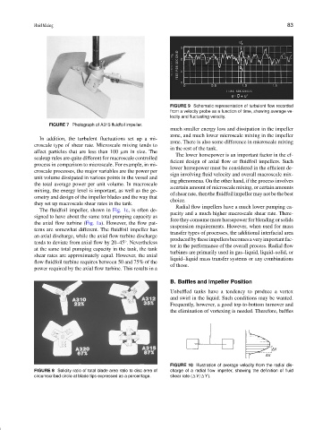
FIGURE 9 Schematic representation of turbulent flow recorded
from a velocity probe as a function of time, showing average ve-
locity and fluctuating velocity.
FIGURE 7 Photograph of A315 fluidfoil impeller.
much smaller energy loss and dissipation in the impeller
zone, and much lower microscale mixing in the impeller
In addition, the turbulent fluctuations set up a mi-
zone. There is also some difference in microscale mixing
croscale type of shear rate. Microscale mixing tends to
in the rest of the tank.
affect particles that are less than 100 µm in size. The
The lower horsepower is an important factor in the ef-
scaleup rules are quite different for macroscale controlled
ficient design of axial flow or fluidfoil impellers. Such
process in comparison to microscale. For example, in mi-
lower horsepower must be considered in the efficient de-
croscale processes, the major variables are the power per
sign involving fluid velocity and overall macroscale mix-
unit volume dissipated in various points in the vessel and
ing phenomena. On the other hand, if the process involves
the total average power per unit volume. In macroscale
a certain amount of microscale mixing, or certain amounts
mixing, the energy level is important, as well as the ge-
of shear rate, then the fluidfoil impeller may not be the best
ometry and design of the impeller blades and the way that
choice.
they set up macroscale shear rates in the tank.
Radial flow impellers have a much lower pumping ca-
The fluidfoil impeller, shown in Fig. 1c, is often de-
pacity and a much higher macroscale shear rate. There-
signed to have about the same total pumping capacity as
fore they consume more horsepower for blending or solids
the axial flow turbine (Fig. 1a). However, the flow pat-
suspension requirements. However, when used for mass
terns are somewhat different. The fluidfoil impeller has
transfer types of processes, the additional interfacial area
an axial discharge, while the axial flow turbine discharge
producedbytheseimpellersbecomesaveryimportantfac-
tends to deviate from axial flow by 20–45 . Nevertheless
◦
tor in the performance of the overall process. Radial flow
at the same total pumping capacity in the tank, the tank
turbines are primarily used in gas–liquid, liquid–solid, or
shear rates are approximately equal. However, the axial
liquid–liquid mass transfer systems or any combinations
flow fluidfoil turbine requires between 50 and 75% of the
of those.
power required by the axial flow turbine. This results in a
B. Baffles and Impeller Position
Unbaffled tanks have a tendency to produce a vortex
and swirl in the liquid. Such conditions may be wanted.
Frequently, however, a good top-to-bottom turnover and
the elimination of vortexing is needed. Therefore, baffles
FIGURE 10 Illustration of average velocity from the radial dis-
FIGURE 8 Solidity ratio of total blade area ratio to disc area of charge of a radial flow impeller, showing the definition of fluid
circumscribed circle at blade tips expressed as a percentage. shear rate ( V/ Y ).