
Page 284 - Academic Press Encyclopedia of Physical Science and Technology 3rd Chemical Engineering
P. 284
P1: FYK/LPB P2: FPP Final
Encyclopedia of Physical Science and Technology EN006C-252 June 27, 2001 14:15
84 Fluid Mixing
are used more often than not. Wall baffles for low-viscosity TABLE I Elements of Mixer Design
systems consist of four baffles, each 1 of the tank diam-
12 Process design
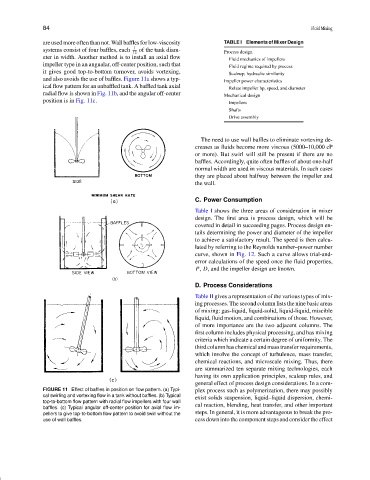
eter in width. Another method is to install an axial flow Fluid mechanics of impellers
impeller type in an angualar, off-center position, such that Fluid regime required by process
it gives good top-to-bottom turnover, avoids vortexing, Scaleup; hydraulic similarity
and also avoids the use of baffles. Figure 11a shows a typ- Impeller power characteristics
ical flow pattern for an unbaffled tank. A baffled tank axial Relate impeller hp, speed, and diameter
radial flow is shown in Fig. 11b, and the angular off-center Mechanical design
position is in Fig. 11c. Impellers
Shafts
Drive assembly
The need to use wall baffles to eliminate vortexing de-
creases as fluids become more viscous (5000–10,000 cP
or more). But swirl will still be present if there are no
baffles. Accordingly, quite often baffles of about one-half
normal width are used in viscous materials. In such cases
they are placed about halfway between the impeller and
the wall.
C. Power Consumption
Table I shows the three areas of consideration in mixer
design. The first area is process design, which will be
covered in detail in succeeding pages. Process design en-
tails determining the power and diameter of the impeller
to achieve a satisfactory result. The speed is then calcu-
lated by referring to the Reynolds number–power number
curve, shown in Fig. 12. Such a curve allows trial-and-
error calculations of the speed once the fluid properties,
P, D, and the impeller design are known.
D. Process Considerations
Table II gives a representation of the various types of mix-
ing processes. The second column lists the nine basic areas
of mixing: gas-liquid, liquid-solid, liquid-liquid, miscible
liquid, fluid motion, and combinations of those. However,
of more importance are the two adjacent columns. The
first column includes physical processing, and has mixing
criteria which indicate a certain degree of uniformity. The
thirdcolumnhaschemicalandmasstransferrequirements,
which involve the concept of turbulence, mass transfer,
chemical reactions, and microscale mixing. Thus, there
are summarized ten separate mixing technologies, each
having its own application principles, scaleup rules, and
general effect of process design considerations. In a com-
FIGURE 11 Effect of baffles in position on flow pattern. (a) Typi- plex process such as polymerization, there may possibly
cal swirling and vortexing flow in a tank without baffles. (b) Typical exist solids suspension, liquid–liquid dispersion, chemi-
top-to-bottom flow pattern with radial flow impellers with four wall
baffles. (c) Typical angular off-center position for axial flow im- cal reaction, blending, heat transfer, and other important
pellers to give top-to-bottom flow pattern to avoid swirl without the steps. In general, it is more advantageous to break the pro-
use of wall baffles. cess down into the component steps and consider the effect