
Page 285 - Academic Press Encyclopedia of Physical Science and Technology 3rd Chemical Engineering
P. 285
P1: FYK/LPB P2: FPP Final
Encyclopedia of Physical Science and Technology EN006C-252 June 27, 2001 14:15
Fluid Mixing 85
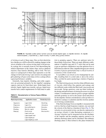
FIGURE 12 Reynolds number–power number curve for several impeller types: D, impeller diameter; N, impeller
rotational speed; ρ, liquid density; µ, liquid viscosity; P, power; and g, gravity constant.
of mixing on each of these steps. One can then determine tion to pumping capacity: There are optimum ratios for
how the process will be affected by making changes in the those kinds of processes. There are many different combi-
mixer variables to the various mixing steps in the process. nations of impeller type and D /T ratios that can be used
In scaleup, this is normally done by first determining the to get an optimum combination once the optimum flow to
relative importance of the various steps, such as chemical fluid shear is achieved. Thus, impeller design is not critical
reaction, mass transfer, blending, and so forth. The next in terms of process performance but is critical in terms of
step is to scaleup each of these steps separately to see the economics of the overall mixer.
change on full-scale mixing. Later sections on scaleup and It is possible to use mixers as low head pumps by suit-
pilot planting will give some ideas on how scaleup affects ably installing them in a draft tube or above the orifice.
typical performance variables. They can then be used to pump large volumes of liquid at
Generally, heat transfer, blending, and solids suspen- low heads.
sion are governed primarily by the impeller’s pumping The fluid mixing process involves three different areas
capacity and not by fluid shear rates. Solid–liquid mass of viscosity which affect flow patterns and scaleup, and
transfer, liquid–liquid mass transfer, and gas–liquid mass two different scales within the fluid itself, macroscale and
transfer have certain requirements for fluid shear in addi- microscale. Design questions come up when looking at
the design and performance of mixing processes in a given
volume. Considerations must be given to proper impeller
TABLE II Characterization of Various Types of Mixing
and tank geometry as well as the proper speed and power
Processes
for the impeller. Similar considerations come up when it is
Physical processing Application classes Chemical process desired to scaleup or scaledown and this involves another
set of mixing considerations.
Suspension Liquid-Solid Dissolving
If the fluid discharge from an impeller is measured with
Dispersion Liquid-Gas Absorption
a device that has a high frequency response, one can track
Emulsions Immiscible liquids Extraction
the velocity of the fluid as a function of time (Fig. 9). The
Blending Miscible liquids Reactions
velocity at a given point in time can then be expressed as
Pumping Fluid motion Heat transfers
an average velocity (¯ν) plus fluctuating component (v ).
Liquid-solid-gas
Average velocities can be integrated across the discharge
Liquid-liquid-solid
of the impeller and the pumping capacity normal to an
Liquid-liquid-gas
arbitrary discharge plane can be calculated. This arbitrary
Liquid-liquid-gas-solid
discharge plane is often defined as the plane bounded by