
Page 309 - Academic Press Encyclopedia of Physical Science and Technology 3rd Chemical Engineering
P. 309
P1: GLQ Final pages
Encyclopedia of Physical Science and Technology En007c-310 June 30, 2001 17:30
Heat Exchangers 255
(D) Tube-side channels and nozzles control the flow of
the tube-side fluid into and out of the tubes. The tube-side
channel may be bolted to the shell by flanges (as shown
in the drawing) or welded directly.
(E) The channel cover bolts over the end of the channel
and contains the tube-side fluid. It may be easily removed
to allow inspection, cleaning, or replacement of the tubes
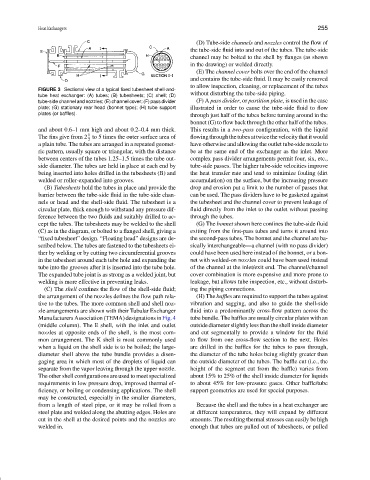
FIGURE 3 Sectional view of a typical fixed tubesheet shell-and-
tube heat exchanger: (A) tubes; (B) tubesheets; (C) shell; (D) without disturbing the tube-side piping.
tube-side channel and nozzles; (E) channel cover; (F) pass divider (F) A pass divider,or partition plate, is used in the case
plate; (G) stationary rear head (bonnet type); (H) tube support illustrated in order to cause the tube-side fluid to flow
plates (or baffles). through just half of the tubes before turning around in the
bonnet (G) to flow back through the other half of the tubes.
and about 0.6–1 mm high and about 0.2–0.4 mm thick. This results in a two-pass configuration, with the liquid
1
The fins give from 2 to 5 times the outer surface area of flowingthroughthetubesattwicethevelocitythatitwould
2
a plain tube. The tubes are arranged in a repeated geomet- have otherwise and allowing the outlet tube-side nozzle to
ric pattern, usually square or triangular, with the distance be at the same end of the exchanger as the inlet. More
between centers of the tubes 1.25–1.5 times the tube out- complex pass divider arrangements permit four, six, etc.,
side diameter. The tubes are held in place at each end by tube-side passes. The higher tube-side velocities improve
being inserted into holes drilled in the tubesheets (B) and the heat transfer rate and tend to minimize fouling (dirt
welded or roller-expanded into grooves. accumulation) on the surface, but the increasing pressure
(B) Tubesheets hold the tubes in place and provide the drop and erosion put a limit to the number of passes that
barrier between the tube-side fluid in the tube-side chan- can be used. The pass dividers have to be gasketed against
nels or head and the shell-side fluid. The tubesheet is a the tubesheet and the channel cover to prevent leakage of
circular plate, thick enough to withstand any pressure dif- fluid directly from the inlet to the outlet without passing
ference between the two fluids and suitably drilled to ac- through the tubes.
cept the tubes. The tubesheets may be welded to the shell (G) The bonnet shown here confines the tube-side fluid
(C) as in the diagram, or bolted to a flanged shell, giving a exiting from the first-pass tubes and turns it around into
“fixed tubesheet” design. “Floating head” designs are de- the second-pass tubes. The bonnet and the channel are ba-
scribed below. The tubes are fastened to the tubesheets ei- sically interchangeable—a channel (with no pass divider)
ther by welding or by cutting two circumferential grooves could have been used here instead of the bonnet, or a bon-
in the tubesheet around each tube hole and expanding the net with welded-on nozzles could have been used instead
tube into the grooves after it is inserted into the tube hole. of the channel at the inlet/exit end. The channel/channel
The expanded tube joint is as strong as a welded joint, but cover combination is more expensive and more prone to
welding is more effective in preventing leaks. leakage, but allows tube inspection, etc., without disturb-
(C) The shell confines the flow of the shell-side fluid; ing the piping connections.
the arrangement of the nozzles defines the flow path rela- (H) The baffles are required to support the tubes against
tive to the tubes. The more common shell and shell noz- vibration and sagging, and also to guide the shell-side
zle arrangements are shown with their Tubular Exchanger fluid into a predominantly cross-flow pattern across the
ManufacturersAssociation(TEMA)designationsinFig.4 tube bundle. The baffles are usually circular plates with an
(middle column). The E shell, with the inlet and outlet outsidediameterslightlylessthantheshellinsidediameter
nozzles at opposite ends of the shell, is the most com- and cut segmentally to provide a window for the fluid
mon arrangement. The K shell is most commonly used to flow from one cross-flow section to the next. Holes
when a liquid on the shell side is to be boiled; the large- are drilled in the baffles for the tubes to pass through,
diameter shell above the tube bundle provides a disen- the diameter of the tube holes being slightly greater than
gaging area in which most of the droplets of liquid can the outside diameter of the tubes. The baffle cut (i.e., the
separate from the vapor leaving through the upper nozzle. height of the segment cut from the baffle) varies from
The other shell configurations are used to meet specialized about 15% to 25% of the shell inside diameter for liquids
requirements in low pressure drop, improved thermal ef- to about 45% for low-pressure gases. Other baffle/tube
ficiency, or boiling or condensing applications. The shell support geometries are used for special purposes.
may be constructed, especially in the smaller diameters,
from a length of steel pipe, or it may be rolled from a Because the shell and the tubes in a heat exchanger are
steel plate and welded along the abutting edges. Holes are at different temperatures, they will expand by different
cut in the shell at the desired points and the nozzles are amounts. The resulting thermal stresses can easily be high
welded in. enough that tubes are pulled out of tubesheets, or pulled