
Page 312 - Academic Press Encyclopedia of Physical Science and Technology 3rd Chemical Engineering
P. 312
P1: GLQ Final pages
Encyclopedia of Physical Science and Technology En007c-310 June 30, 2001 17:30
258 Heat Exchangers
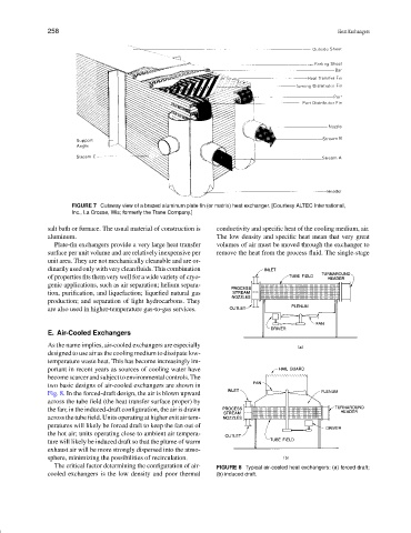
FIGURE 7 Cutaway view of a brazed aluminum plate fin (or matrix) heat exchanger. [Courtesy ALTEC International,
Inc., La Crosse, Wis; formerly the Trane Company.]
salt bath or furnace. The usual material of construction is conductivity and specific heat of the cooling medium, air.
aluminum. The low density and specific heat mean that very great
Plate-fin exchangers provide a very large heat transfer volumes of air must be moved through the exchanger to
surface per unit volume and are relatively inexpensive per remove the heat from the process fluid. The single-stage
unit area. They are not mechanically cleanable and are or-
dinarilyusedonlywithverycleanfluids.Thiscombination
of properties fits them very well for a wide variety of cryo-
genic applications, such as air separation; helium separa-
tion, purification, and liquefaction; liquefied natural gas
production; and separation of light hydrocarbons. They
are also used in higher-temperature gas-to-gas services.
E. Air-Cooled Exchangers
As the name implies, air-cooled exchangers are especially
designed to use air as the cooling medium to dissipate low-
temperature waste heat. This has become increasingly im-
portant in recent years as sources of cooling water have
becomescarcerandsubjecttoenvironmentalcontrols.The
two basic designs of air-cooled exchangers are shown in
Fig. 8. In the forced-draft design, the air is blown upward
across the tube field (the heat transfer surface proper) by
the fan; in the induced-draft configuration, the air is drawn
across the tube field. Units operating at higher exit air tem-
peratures will likely be forced draft to keep the fan out of
the hot air; units operating close to ambient air tempera-
ture will likely be induced draft so that the plume of warm
exhaust air will be more strongly dispersed into the atmo-
sphere, minimizing the possibilities of recirculation.
The critical factor determining the configuration of air- FIGURE 8 Typical air-cooled heat exchangers: (a) forced draft;
cooled exchangers is the low density and poor thermal (b) induced draft.