
Page 315 - Academic Press Encyclopedia of Physical Science and Technology 3rd Chemical Engineering
P. 315
P1: GLQ Final pages
Encyclopedia of Physical Science and Technology En007c-310 June 30, 2001 17:30
Heat Exchangers 261
where L is the tube length. However, the equation can be
applied with small modifications to tubes with external
fins, where A o now is the total heat transfer surface on
the outside of the tube, including the fins. Corresponding
to Eq. (5), the overall heat transfer coefficient could have
been based on the outside area of the heat transfer surface
A o :
1
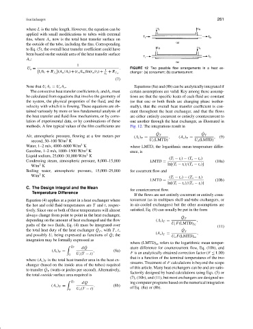
. FIGURE 12 Two possible flow arrangements in a heat ex-
1
U o =
(A o /A i )+(r o /k w )ln(r o /r i )+
1/h i + R f i + R f o changer: (a) concurrent; (b) countercurrent.
h o
(7)
Note that U i A i = U o A o . Equations (8a) and (8b) can be analytically integrated if
The convective heat transfer coefficients h i and h o must certain assumptions are valid. Key among these assump-
be calculated from equations that involve the geometry of tions are that the specific heats of each fluid are constant
the system, the physical properties of the fluid, and the (or that one or both fluids are changing phase isother-
velocity with which it is flowing. These equations are ob- mally), that the overall heat transfer coefficient is con-
tained variously by more or less fundamental analysis of stant throughout the heat exchanger, and that the flows
the heat transfer and fluid flow mechanisms, or by corre- are either entirely cocurrent or entirely countercurrent to
lation of experimental data, or by combinations of these one another through the heat exchanger, as illustrated in
methods. A few typical values of the film coefficients are Fig. 12. The integrations result in
Q ˙ Q ˙
Air, atmospheric pressure, flowing at a few meters per (A i ) = T , (A o ) = T , (9)
T
T
2
second, 50–100 W/m K U i (LMTD) U o (LMTD)
2
Water, 1–2 m/s, 4000–6000 W/m K where LMTD, the logarithmic mean temperature differ-
2
Gasoline, 1–2 m/s, 1000–1500 W/m K ence, is
2
Liquid sodium, 25,000–30,000 W/m K
(T i − t i ) − (T o − t o )
Condensing steam, atmospheric pressure, 8,000–15,000 LMTD = (10a)
2
W/m K ln[(T i − t i )/(T o − t o )]
Boiling water, atmospheric pressure, 15,000–25,000 for cocurrent flow and
2
W/m K (T i − t o ) − (T o − t i )
LMTD = (10b)
ln[(T i − t o )/(T o − t i )]
C. The Design Integral and the Mean
for countercurrent flow.
Temperature Difference
If the flows are not entirely cocurrent or entirely coun-
Equation (4) applies at a point in a heat exchanger where tercurrent (as in multipass shell-and-tube exchangers, or
the hot and cold fluid temperatures are T and t, respec- in air-cooled exchangers) but the other assumptions are
tively. Since one or both of these temperatures will almost satisfied, Eq. (9) can usually be put in the form
always change from point to point in the heat exchanger,
Q ˙ T
depending on the amount of heat exchanged and the flow (A i ) = ,
T
paths of the two fluids, Eq. (4) must be integrated over U i F(LMTD) cc (11)
˙
the total heat duty of the heat exchanger Q , with T , t, Q ˙ T
T
˙
T
and possibly U i being expressed as functions of Q; the (A o ) = ,
U o F(LMTD) cc
integration may be formally expressed as
where (LMTD) cc refers to the logarithmic mean temper-
dQ ature difference for countercurrent flow, Eq. (10b), and
˙ Q T ˙
(A i ) = , (8a) F is an analytically obtained correction factor (F ≤ 1.00)
T
0 U i (T − t)
that is a function of the terminal temperatures of the two
where (A i ) is the total heat transfer area in the heat ex- streams. Treatment of F calculations is beyond the scope
T
changer (based on the inside area of the tubes) required of this article. Many heat exchangers can be and are satis-
˙
to transfer Q (watts or joules per second). Alternatively, factorily designed by hand calculations using Eqs. (5) or
T
the total outside surface area required is
(7), (10b), and (11), but most exchangers are designed us-
dQ ing computer programs based on the numerical integration
˙ Q T
(A o ) = . (8b) of Eq. (8a) or (8b).
T
0 U o (T − t)