
Page 311 - Academic Press Encyclopedia of Physical Science and Technology 3rd Chemical Engineering
P. 311
P1: GLQ Final pages
Encyclopedia of Physical Science and Technology En007c-310 June 30, 2001 17:30
Heat Exchangers 257
apart or bowed, or the shells badly distorted. The fixed-
tubesheet exchanger shown in Fig. 3 can only be used with
small temperature differences (typically less than 50 C
◦
between the entering fluid streams). Other configurations
must be used when thermal stress is a problem.
FIGURE 6 Two types of gasketed plates for the gasketed-
The U-tube exchanger (Fig. 4) is the best solution to the plate heat exchanger: (a) parallel-corrugated plate; (b) cross-
thermal stress problem, becauseeachtubeis free to expand corrugated plate (“herringbone” pattern or “chevron”).
or contract independently of the others or of the shell.
However,therearedisadvantagestotheU-tubeexchanger: metal plate separating the two fluids. Each fluid flows be-
the tubes cannot be mechanically cleaned around the bend, tween adjacent pairs of plates, the gasketing arrangements
the inner tubes cannot be individually replaced, the long- around the corner ports determining which fluid will flow
radius U-tubes are particularly subject to vibration, and between each pair, and the gasket around the outer edge
single-pass tube-side flow is not possible. sealing each fluid against leakage to the atmosphere. The
Therefore, several different designs of “floating-head” individual plates are corrugated so that they will mutually
exchangers (Fig. 4, rear-end head types P, S, T, and W) support each other against pressure differences between
are commonly used to relieve the thermal stress problem; the two fluids. The corrugations cause the flow to be very
the characteristic feature is that the assembly of the rear turbulent, resulting in high heat transfer coefficients and
tubesheet and the associated head is not mechanically con- high pressure drops. The strong turbulence also tends to
nected to the shell. The choice among the configurations minimize fouling on the surface.
depends on the pressures, the temperatures, and the de- The stack of plates is pressed together by the compres-
gree of danger should leakage occur to the atmosphere or sion bolts to seat the gaskets. The plates may be made
between the two fluids. of any metal that can be pressed and provide more heat
To reemphasize, shell-and-tube heat exchangers are the transfer surface per unit mass of metal and per unit volume
most commonly employedtypein the chemicalprocessin- than a shell-and-tube exchanger. Therefore, gasketed plate
dustries because they are so adaptable to such wide ranges exchangers cost much less per unit surface area than shell-
of conditions. and-tube exchangers if a metal other than low-carbon steel
must be used. However, the gasket (usually made of a syn-
thetic rubber or polymer) limits plate heat exchangers to
C. Gasketed-Plate Heat Exchangers
pressures below 20 atm (2 MPa) and temperatures below
◦
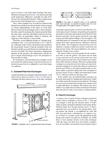
Agasketed-plateheatexchangerisillustratedinFig.5,and 175 C, with lower limits for the larger sizes.
representative plates are shown in Fig. 6. In this type of In the smaller sizes, the gasketed plate exchanger can
exchanger, the heat transfer surface is the thin corrugated be easily taken apart for cleaning and sterilization, so they
are widely used in the food processing industry. The larger
sizes are used in chemical processing where stainless steel
or other high alloys are required. The largest sizes (up to
2
2200 m in a single unit) are often constructed of titanium
and used with sea water on one side as a cooling medium.
D. Plate-Fin Exchanger
A cutaway view of a plate-fin heat exchanger (sometimes
called a matrix exchanger) is shown in Fig. 7. This type
of exchanger is built up with alternate layers of matrix
sheets (usually corrugated aluminum) and parting sheets.
Different fluids flow through alternate layers of matrix,
separated from one another by the parting sheets. Seal-
ing against the outside is accomplished by solid side
bars, and each fluid is distributed to its respective lay-
ers of matrix by a header system. By appropriate header
design and location, the plate-fin exchanger can handle
three or more separate streams in the same exchanger.
After the layers are built up to the desired configura-
FIGURE 5 Exploded view of a gasketed-plate heat exchanger. tion, the assembly is permanently brazed together using a