
Page 308 - Academic Press Encyclopedia of Physical Science and Technology 3rd Chemical Engineering
P. 308
P1: GLQ Final pages
Encyclopedia of Physical Science and Technology En007c-310 June 30, 2001 17:30
254 Heat Exchangers
erosion and vibration problems, it is important to limit
velocities, especially in certain critical areas near the noz-
zles and wherever the flow is forced to change direction in
the heat exchanger. The exchanger must also be designed
either to minimize fouling or to withstand the mechanical
effects as fouling does develop.
3. The heat exchanger must be maintainable. It must
allow mechanical or chemical cleaning if the heat transfer
surface becomes fouled, and it must permit replacement
of the tubes, gaskets, and any other components that may
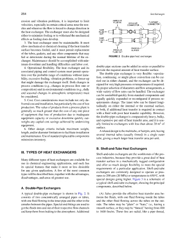
fail or deteriorate during the normal lifetime of the ex- FIGURE 2 Double-pipe heat exchanger.
changer. Maintenance should be accomplished with min-
imum downtime and handling difficulties and labor cost.
double-pipe sections can be added in series or parallel to
4. Operational flexibility. The heat exchanger and its
provide the required amount of heat transfer surface.
associated piping and control system must permit opera-
The double-pipe exchanger is very flexible: vaporiza-
tion over the probable range of conditions without insta-
tion, condensing, or single-phase convection can be car-
bility, excessive fouling, vibration problems, or freeze-up
ried out in either channel, and the exchanger can be de-
that might damage the exchanger itself. Both changes in
signed for very high pressures or temperatures if required.
process conditions (e.g., changes in process flow rate or
By proper selection of diameters and flow arrangements, a
composition) and in environmental conditions (e.g., daily
wide variety of flow rates can be handled. The exchanger
and seasonal changes in atmospheric temperature) must
can be assembled quickly from standard components and
be considered.
equally quickly expanded or reconfigured if process re-
5. Cost. Cost considerations must include not only de-
quirements change. The inner tube can be finned longi-
liveredcostandinstallation,butparticularlythecostoflost
tudinally on either the internal or the external surface,
production. The value of products from a process plant is
or both, if additional heat transfer is required in contact
generally so much greater than the cost of any one piece
with a fluid with poor heat transfer capability. However,
of equipment that loss of production due to inadequate
the double-pipe exchanger is comparatively heavy, bulky,
equipment capacity or excessive downtime quickly out-
and expensive per unit of heat transfer area, and it is usu-
weighs any capital cost savings achieved by undersizing
2
ally limited to exchangers with less than about 20 m of
equipment.
surface.
6. Other design criteria include maximum weight,
A related design is the multitube, or hairpin, unit,having
length, and/or diameter limitations to facilitate installation
several internal tubes (usually finned) in a single outer
andmaintenance.Useofstandardreplaceablecomponents
tube, giving a much larger heat transfer area per unit.
minimizes inventory.
B. Shell-and-Tube Heat Exchangers
III. TYPES OF HEAT EXCHANGERS
Shell-and-tube exchangers are the workhorses of the pro-
cess industries, because they provide a great deal of heat
Many different types of heat exchangers are available for
transfer surface in a mechanically rugged configuration
use in chemical engineering applications, and each has
and offer so much design flexibility to meet the special
its special features that make it more or less desirable requirements of a particular application. Shell-and-tube
for any given application. A few of the most common
exchangers are commonly designed to operate at pres-
types will be described here, together with the advantages,
◦
sures to 200 atm (20 MPa) or temperatures to 650 C, with
disadvantages, and areas of greatest use.
special designs going higher. Figure 3 is a schematic of
a typical shell-and-tube exchanger, showing the principal
components, described below.
A. Double-Pipe Exchangers
A typical double-pipe exchanger is shown in Fig. 2. It (A) Tubes provide the effective heat transfer area be-
consists of two concentrically arranged pipes or tubes, tween the fluids, with one fluid flowing inside the tubes
with one fluid flowing in the inner pipe and the other in the and the other fluid flowing across the tubes on the out-
annulus between the pipes. Special end fittings are used to side. The tubes may be “plain” or “bare,” i.e., having a
get the fluids into and out of their respective flow channels smooth surface, or they may be “finned,” having from 400
and keep them from leaking to the atmosphere. Additional to 1600 fins/m. These fins are radial, like a pipe thread,