
Page 304 - Academic Press Encyclopedia of Physical Science and Technology 3rd Chemical Engineering
P. 304
P1: FYK/LPB P2: FPP Final
Encyclopedia of Physical Science and Technology EN006C-252 June 27, 2001 14:15
104 Fluid Mixing
overall flow pattern. It is important that a careful bal-
ance be made between the time and expense of calculat-
ing these flow patterns with computational fluid dynamics
compared to their applicability to an actual industrial pro-
cess. The future of computational fluid dynamics appears
very encouraging and a reasonable amount of time and
effort placed in this regard can yield immediate results as
well as potential for future process evaluation.
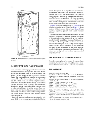
Figures 38–40 show some approaches. Figure 38 shows
velocity vectors for an A310 impeller. Figure 39 shows
contours of kinetic energy of turbulence. Figure 40 uses
a particle trajectory approach with neutral buoyancy
particles.
Numerical fluid mechanics can define many of the fluid
mechanics parameters for an overall reactor system. Many
of the models break the mixing tank up into small mi-
crocells. Suitable material and mass transfer balances be-
tween these cells throughout the reactor are then made.
This can involve long and massive computational require-
ments. Programs are available that can give reasonably
acceptable models of experimental data taken in mixing
vessels. Modeling the three-dimensional aspect of a flow
pattern in a mixing tank can require a large amount of
computing power.
SEE ALSO THE FOLLOWING ARTICLES
FIGURE 40 A particle trajectory approach with neutral buoyancy
particles.
FLUID DYNAMICS • FLUID DYNAMICS (CHEMICAL ENGI-
NEERING)•FLUIDINCLUSIONS•HEATTRANSFER•REAC-
TORS IN PROCESS ENGINEERING • SOLVENT EXTRACTION
XI. COMPUTATIONAL FLUID DYNAMICS
There are several software programs that are available to BIBLIOGRAPHY
model flow patterns of mixing tanks. They allow the pre-
diction of flow patterns based on certain boundary con- Dickey, D. S. (1984). Chem. Eng. 91, 81.
ditions. The most reliable models use accurate fluid me- Mcmullen, R., and Weber, M. (1935). Chem. Metall. Eng. 42, 254–257.
Nagata, S. (1975). “Mixing Principles and Applications,” Halsted Press,
chanics data generated for the impellers in question and
New York.
a reasonable number of modeling cells to give the overall Nienow, A. W., Hunt, G., and Buckland, B. C. (1994). Biotech, Bio Eng.
tank flow pattern. These flow patterns can give velocities, 44, No. 10, 1177.
streamlines, and localized kinetic energy values for the Oldshue, J. Y. (1996). Chem. Eng. Prog. Vol. 92.
systems. Their main use at the present time is to look at Oldshue, J. Y. (1980). Chem. Eng. Prog. June, pp. 60–64.
Oldshue, J. Y. (1981). Chemtech. Sept., pp. 554–561.
the effect of making changes in mixing variables based
Oldshue, J. Y. (1981). Chem. Eng. Prog. May, pp. 95–98.
on doing certain things to the mixing process. These pro-
grams can model velocity, shear rates, and kinetic energy, Oldshue, J. Y. (1983). “Fluid Mixing Technology,” McGraw-Hill,
but probably cannot adapt to the actual chemistry of diffu- New York.
sion or mass transfer kinetics of actual industrial process Patwardhan, A. W., Joshi, J. B. (1999). Ind. Eng. Chem. Pres. 38, 49–80.
Tatterson, G. B. (1991). Fluid Mixing and Gas Dispersion in Agitated
at the present time.
Tanks.
Relatively uncomplicated transparent tank studies with Uhl, V. W., and Grey, J. B. (1966). “Mixing Theory and Practice,” Vols. I,
tracer fluids or particles can give a similar feel for the II, and III, Academic Press, New York.