
Page 299 - Academic Press Encyclopedia of Physical Science and Technology 3rd Chemical Engineering
P. 299
P1: FYK/LPB P2: FPP Final
Encyclopedia of Physical Science and Technology EN006C-252 June 27, 2001 14:15
Fluid Mixing 99
done on the proper design and flaring of these tubes for
special applications. The main use of draft tube circula-
tors has been in precipitators and crystallizers. A further
requirement is that the liquid level be relatively uniform
in depth above the top of the draft tube, which means that
variable liquid levels are not practical with draft tube sys-
tems. In addition, slots are often provided at the bottom
of the draft tube, so that should a power failure occur and
solids settle at the bottom of the tank, flow can be passed
through these slots and scrub out particles at the bottom
of the tank for resuspension.
Sometimes it is desired to have a large working area in
a tank where, for example, a conveyor belt containing car
FIGURE 31 Typical head flow curve for mixing impeller and draft bodies can be passed through for electrostatic painting.
tube with corresponding system curves. One way to accomplish this is to put a series of propeller
mixers in a side arm of the long side of the tank, so that
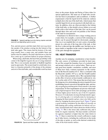
flow, and also power, and then make their own way down the flow is directed into the middle zone, but there are no
the outside of the annulus coming into the bottom of the mixer shafts or impellers in the center to impede the flow
draft tube again. This means that the bottom of the tank of the parts through the equipment.
must usually have a steep cone, and suitable flares and
baffles must be added to the draft tube bottom so that the VIII. HEAT TRANSFER
flow comes up in a uniform fashion for proper efficiency.
When using a draft tube, the back flow possibility in the Another area for pumping consideration is heat transfer.
center of the impeller requires the use of a large-diameter The only sources of turbulence provided in heat trans-
hub. This is not normally desirable in fluidfoil impellers fer are flow around the boundary layer of a jacketed tank
used in open tanks. The system head for a draft tube circu- and around a helical coil or vertical tubes. There are sev-
lator is a function primarily of the design of the entrance eral good heat transfer correlations available, and most
and exit of the draft tube, and considerable work has been of them have fairly common exponents on the correla-
tion of the Nusselt number hD/k. This is correlated with
2
the Reynolds number ND p /µ and the Prandtl number
Cpµ/k plus other geometric ratios. The exponential slope
on the effect of power on heat transfer coefficient is very
low (on the order of 0.2). This means that most heat trans-
fer design involves determining the mixer required for just
establishing forced convection through the tank, and usu-
ally not going beyond that point if heat transfer is the main
requirement. If other requirements are present which indi-
cate a high horsepower level, then advantage can be taken
of these higher power levels by use of the 0.2 exponent.
However, if it is desired to increase the heat transfer capac-
ity of a mixing tank, it is normally done by increasing or
changing the heat transfer surface, since very little can be
done by changing the mixer power level. Figure 33 gives
a good working correlation for the effect of viscosity on
both heating and cooling coefficients for helical coil sys-
tems. Jacketed tanks have values about two-thirds of those
in Fig. 33. This is the mixer side coefficient only, and it
holds for organic materials, The heat transfer coefficient
for aqeuous materials is higher than the value shown in
Fig. 33. Bear in mind that the overall coefficient is made
up of other factors, including the coefficient on the inside
of the tube or jacket, as well as the thermal conductivity
FIGURE 32 Typical axial flow impeller and draft tube. value of the heat transfer surface.