
Page 298 - Academic Press Encyclopedia of Physical Science and Technology 3rd Chemical Engineering
P. 298
P1: FYK/LPB P2: FPP Final
Encyclopedia of Physical Science and Technology EN006C-252 June 27, 2001 14:15
98 Fluid Mixing
FIGURE 29 Typical orientation of side-entering mixer in large
petroleum storage tanks.
top-to-bottom flow pattern. However, even when this is
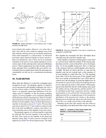
FIGURE 30 Schematic illustration of total flow in mixing tank as
done, there still are some relatively stagnant areas of the compared to impeller flow.
tank, and side-entering mixers are not usually satisfactory
when solid suspension is a critical factor. As discussed flow impeller has essentially less flow and higher shear
previously, larger-diameter impellers at slower speeds re- rates than does the axial flow impeller type.
quire less horsepower, and so there can be an economic If the impeller is required to pump against a static head
evaluation of the power versus capital equipment cost for or a friction head within the channel of the mixing tank,
various types of side-entering mixers and a given blending then there must be a series of head flow curves developed,
process. Typical applications are crude oil tanks, gasoline (Fig. 31) for the impeller being used. This is a function
tanks, and paper stock. In addition, they are used for vari- of the clearance between a radial impeller and a horizon-
ous kinds of process applications where the advantages are tal baffle. The hole in it allows the flow to come into the
considerable over the use of a conventional top-entering impeller zone but not circulate back, or the clearance of
mixer. an axial impeller in a draft tube (Fig. 32). The operating
point, then, will be the intersection of the impeller head
VII. FLUID MOTION flow curve and the system head flow curve. Draft tube cir-
culators have the advantage of giving the highest flow in
Many times the objective is to provide a pumping action the annulus for a given level of power or requiring the least
throughout the tank. The pumping capacity of impellers power to provide a given flow of the annulus. When pump-
can be measured by photographic techniques, hot wire or ing down the draft tube, the flow in the annulus must equal
hot film velocity meters, or laser Doppler velocity meters. the settling velocity of the particles, and the total flow can
There is no generally agreed upon definition of the dis- be calculated on that basis. In practice, the flow coming
charge areas for impellers, so that the primary pumping up the annulus is not a uniform flat velocity profile; so that
capacity of mixing impellers varies somewhat, depending additional total flow is needed because of the nonuniform
onthedefinitionusedfordischargearea.Thereisconsider- distribution of the upward axial velocity to the annulus.
able entrainment of fluid in the tank, due to the jet action of Pumping down the draft tube allows the tank bottom to be
the flow from the impeller. Figure 30 shows the increase in flat or have very small conical fillets at the sidewalls.
total flow in the tank at various D /T ratios. This also indi- Pumping up the draft tube requires that the solids are
cates that at about 0.6 D /T ratio further increases in total to be suspended in the draft tube with a much lower total
flow in the tank are difficult to achieve, since there is no
more entraining action of the impeller in the total system. TABLE VI Constant in Flow versus Speed and
Diameter of Various Mixing Impellers
The pumping capacity of a mixing impeller is specified
by either the flow from the impeller or the total flow of Figure K
the tank. Flow varies for any impeller as the speed and
1a 0.8
diameter cubed. Table VI gives some for constants in the
1b 0.6
3
equation Q = KND for various impeller types. The radial