
Page 296 - Academic Press Encyclopedia of Physical Science and Technology 3rd Chemical Engineering
P. 296
P1: FYK/LPB P2: FPP Final
Encyclopedia of Physical Science and Technology EN006C-252 June 27, 2001 14:15
96 Fluid Mixing
VI. BLENDING
A. Low-Viscosity Blending
Low-viscosity blending involves evaluation of the degree
of uniformity required and the operating cycle. There
is a difference in performance, depending on whether
the materials to be blended are added continuously and
FIGURE 26 Illustration of optimum shear stress in a mixing zone
of various types of countercurrent liquid–liquid extraction columns.
columns, is the ability to get a smaller volume for the
same degree of extraction. However, if an attempt is made
to use too much energy, then problems of settling char-
acteristics are encountered, and this negates the advan-
tages of the mixed system many times. In the mining
industry, it is quite typical to use mixer settlers. These
usually involve an extraction step, a scrubbing step, and
then a stripping step. Usually the requirement is for only
one or two stages in each of these areas with the use
of very selective ion exchange chemicals in the system.
To eliminate interstage pumps a pump–mixer is used in
which some of the head component of the impeller is
converted to a static head so that fluids can be pumped
against small static heads in the mixers and settlers of the
whole train. This has worked well in many applications,
although there is a potential problem that the conditions
required for effective pumping are not optimum for the
mixing that is required in the mixing stage, and there may
besomedesignparametersthataredifficulttosatisfyinthe
systems.
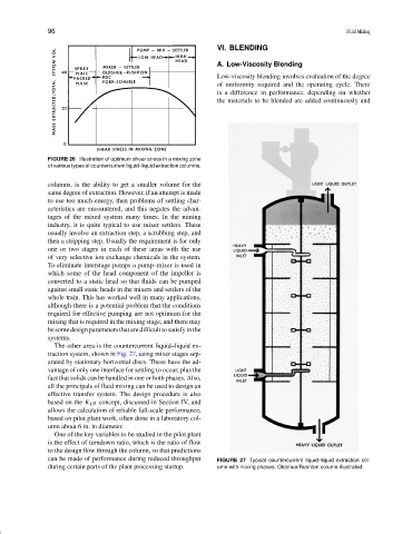
The other area is the countercurrent liquid–liquid ex-
traction system, shown in Fig. 27, using mixer stages sep-
arated by stationary horizontal discs. These have the ad-
vantage of only one interface for settling to occur, plus the
fact that solids can be handled in one or both phases. Also,
all the principals of fluid mixing can be used to design an
effective transfer system. The design procedure is also
based on the K L a concept, discussed in Section IV, and
allows the calculation of reliable full-scale performance,
based on pilot plant work, often done in a laboratory col-
umn about 6 in. in diameter.
One of the key variables to be studied in the pilot plant
is the effect of turndown ratio, which is the ratio of flow
to the design flow through the column, so that predictions
can be made of performance during reduced throughput FIGURE 27 Typical countercurrent liquid–liquid extraction col-
during certain parts of the plant processing startup. umn with mixing phases: Oldshue/Rushton column illustrated.