
Page 294 - Academic Press Encyclopedia of Physical Science and Technology 3rd Chemical Engineering
P. 294
P1: FYK/LPB P2: FPP Final
Encyclopedia of Physical Science and Technology EN006C-252 June 27, 2001 14:15
94 Fluid Mixing
time in a large mixing vessel equipped with A315 im-
pellers will be about one-third that of the blend time in the
same vessel equipped with R100 impellers. Blending is
relatively long on full scale compared to pilot scale, so the
improvement in blending characteristics on full scale can
lead to a much more uniform blending condition. Many
fermentations are responsive to improved blending and
this is another factor in addition to the requirement of
gas–liquid mass transfer that exists in many fermentation
systems as well as in other gas–liquid operations.
A. Combination of Gas–Liquid
and Solids Systems
As mentioned previously, axial flow impellers are typi-
FIGURE 22
cally used for solids suspension. It is also typical to use
radial flow impellers for gas–liquid mass transfer. In com-
This allows the calculation of full-scale mixers when pilot bination gas-liquid-solid systems, it is more common to
plant data is available in that particular fluid system. use radial flow impellers because the desired power level
The curve shown in Fig. 22, for an R100 impeller illus- for mass transfer normally accomplishes solids suspen-
trates that there is a break point in the relationship with sion as well. The less effective flow pattern of the axial
K G a versus the power level at the point where the power flow impeller is not often used in high-uptake-rate sys-
of the mixer is approximately three times the power in the tems for industrial mass transfer problems. There is one
expanding gas stream. The power per unit volume for an exception, and that is in the aeration of waste. The up-
expanding gas stream at pressures from 1 to 100 psi can take rate in biological oxidation systems is on the order
be expressed by the equation P /V (HP/1000 gal) = 15F of 30 ppm/hr, which is about 1 to 1 the rate that may be
2 10
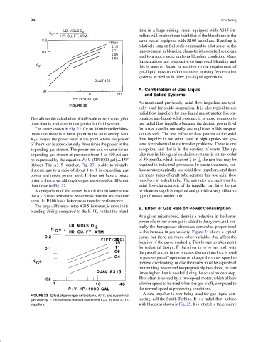
(ft/sec). The A315 impeller, Fig. 23, is able to visually required in industrial processes. In waste treatment, sur-
disperse gas to a ratio of about 1 to 1 in expanding gas face aerators typically use axial flow impellers, and there
power and mixer power level. It does not have a break are many types of draft tube aerators that use axial flow
point in the curve, although slopes are somewhat different impellers in a draft tube. The gas rates are such that the
than those in Fig. 22. axial flow characteristic of the impeller can drive the gas
A comparison of the curves is such that in some areas to whatever depth is required and provide a very effective
the A315 has a somewhat better mass transfer and in other type of mass transfer unit.
areas the R100 has a better mass transfer performance.
The large difference in the A315, however, is more in its
B. Effect of Gas Rate on Power Consumption
blending ability compared to the R100, so that the blend
At a given mixer speed, there is a reduction in the horse-
power of a mixer when gas is added to the system, and nor-
mally the horsepower decreases somewhat proportional
to the increase in gas velocity. Figure 24 shows a typical
curve, but there are many other variables that affect the
location of the curve markedly. This brings up a key point
for industrial design. If the mixer is to be run both with
the gas off and on in the process, then an interlock is used
to prevent gas-off operation or change the mixer speed to
prevent overloading, or else the mixer must be capable of
transmitting power and torque possibly two, three, or four
times higher than is needed during the actual process step.
This often is solved by a two-speed motor, which allows
a lower speed to be used when the gas is off, compared to
the normal speed at processing conditions.
A new impeller is now being used for gas-liquid con-
FIGURE 23 Effect of power per unit volume, P/V, and superficial
gas velocity, F, on the mass transfer coefficient K G a, for dual A315 tacting, call the Smith Turbine. It is a radial flow turbine
impellers. with blades as shown in Fig. 25. It is rotated in the concave