
Page 297 - Academic Press Encyclopedia of Physical Science and Technology 3rd Chemical Engineering
P. 297
P1: FYK/LPB P2: FPP Final
Encyclopedia of Physical Science and Technology EN006C-252 June 27, 2001 14:15
Fluid Mixing 97
uniformly into the tank, with the tank originally in motion
or whether the tank has become stratified during the fill-
ing application, and mixing must be accomplished with a
stratified liquid level situation. In general, blend time is
reduced at constant mixer power with larger D /T ratios.
The exponent on D /T with blend time is approximately
−1.5, with the range observed experimentally of from 0.5
to 3.0. This leads to the fact that larger impellers running at
slow speeds require less power than a small mixer running
at high speed for the same blend time. In that case, there is
an evaluation needed which relates the capital cost of the
equipment, represented by the torque required in the mixer
drive which is usually greatest for the big impeller, versus
the cost of horsepower, which is usually greatest for the
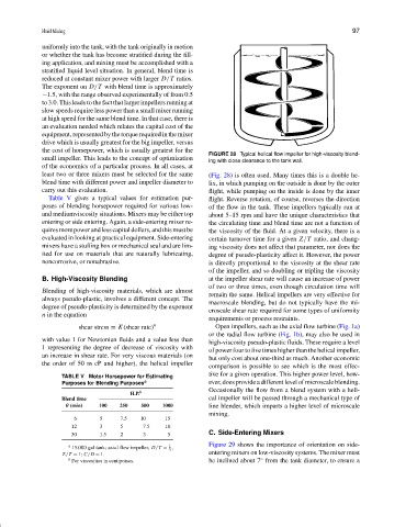
FIGURE 28 Typical helical flow impeller for high-viscosity blend-
small impeller. This leads to the concept of optimization ing with close clearance to the tank wall.
of the economics of a particular process. In all cases, at
least two or three mixers must be selected for the same (Fig. 28) is often used. Many times this is a double he-
blend time with different power and impeller diameter to lix, in which pumping on the outside is done by the outer
carry out this evaluation. flight, while pumping on the inside is done by the inner
Table V gives a typical values for estimation pur- flight. Reverse rotation, of course, reverses the direction
poses of blending horsepower required for various low- of the flow in the tank. These impellers typically run at
and mediumviscosity situations. Mixers may be either top about 5–15 rpm and have the unique characteristics that
entering or side entering. Again, a side-entering mixer re- the circulating time and blend time are not a function of
quiresmorepowerandlesscapitaldollars,andthismustbe the viscosity of the fluid. At a given velocity, there is a
evaluated in looking at practical equipment. Side-entering certain turnover time for a given Z/T ratio, and chang-
mixers have a stuffing box or mechanical seal and are lim- ing viscosity does not affect that parameter, nor does the
ited for use on materials that are naturally lubricating, degree of pseudo-plasticity affect it. However, the power
noncorrosive, or nonabrasive. is directly proportional to the viscosity at the shear rate
of the impeller, and so doubling or tripling the viscosity
B. High-Viscosity Blending at the impeller shear rate will cause an increase of power
of two or three times, even though circulation time will
Blending of high-viscosity materials, which are almost
remain the same. Helical impellers are very effective for
always pseudo-plastic, involves a different concept. The
macroscale blending, but do not typically have the mi-
degree of pseudo-plasticity is determined by the exponent
croscale shear rate required for some types of uniformity
n in the equation
requirements or process restraints.
shear stress = K(shear rate) n Open impellers, such as the axial flow turbine (Fig. 1a)
or the radial flow turbine (Fig. 1b), may also be used in
with value 1 for Newtonian fluids and a value less than
high-viscosity pseudo-plastic fluids. These require a level
1 representing the degree of decrease of viscosity with
of power four to five times higher than the helical impeller,
an increase in shear rate. For very viscous materials (on
but only cost about one-third as much. Another economic
the order of 50 m cP and higher), the helical impeller
comparison is possible to see which is the most effec-
tive for a given operation. This higher power level, how-
TABLE V Motor Horsepower for Estimating
Purposes for Blending Purposes a ever, does provide a different level of microscale blending.
Occasionally the flow from a blend system with a heli-
H.P. b
Blend time cal impeller will be passed through a mechanical type of
θ (min) 100 250 500 1000 line blender, which imparts a higher level of microscale
mixing.
6 5 7.5 10 15
12 3 5 7.5 10
C. Side-Entering Mixers
30 1.5 2 3 5
Figure 29 shows the importance of orientation on side-
1
a 15,000 gal tank; axial flow impeller, D/T = ,
3
Z/T = 1; C/D = 1. entering mixers on low-viscosity systems. The mixer must
◦
b For viscosities in centipoises. be inclined about 7 from the tank diameter, to ensure a