
Page 28 - Academic Press Encyclopedia of Physical Science and Technology 3rd Analytical Chemistry
P. 28
P1: GJB Revised Pages
Encyclopedia of Physical Science and Technology En001f25 May 7, 2001 13:58
Analytical Chemistry 567
Other sources are field desorption, spark source, thermal are brought to a focus close to where the ion detector is
ionization, fast atom bombardment, and secondary ion located. Thus, the analyzer separates the ions into streams
mass spectrometry (see SIMS, Section G.4, Surface Anal- of different M/e,
ysis). 2 2
M/e = H r /2V,
where M is the mass of the ion, e is the charge, H is
2. The Spectrometer
the magnetic field, r is the radius of curvature of the an-
The purpose of the spectrometer is to separate the ions alyzer tube, and V is the accelerating potential employed
emanating from the ion source as efficiently as possible. in the ion source. Usually, V is swept to obtain a mass
Quantitatively, this is expressed as the resolving power spectrum. In the time-of-flight mass spectrometer, ions
of the instrument, which is defined as the ratio M/ M, of different mass, which are produced by pulsed electron
where M and M + M are the mass numbers of two beam impact in the ion source, are accelerated to the same
neighboring peaks of equal intensity in the spectrum. kinetic energy. The ions are then allowed to drift in space
The key factor here is the ability to distinguish M and down a tube of particular length before they are detected
M + M; usually, this is said to be achieved when the (Fig. 19b). Because they have different velocity, the transit
“valley” between the two peaks is no more than 10% of time t varies as
the intensity of M or M + M. Resolution is controlled 1/2
M 1
by a number of instrumental factors, including the method t = L µsec.
of ion separation. e 2V
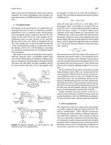
One widely used system of separation is the magnetic This instrument is useful for the study of fast reactions. An
deflection apparatus. Here, a controllable magnetic field additional spectrometer known as the quadrupole device
causes ions to deflect along curved paths according to their is based on the passage of ions through a region between
mass-to-charge ratio. The instrument is designed such that four, short parallel metal rods of alternating electrical volt-
only those ions that follow the path coinciding with the age and provides low resolving power. This is widely used
arc of the analyzer tube (Fig. 19a) in the magnetic field because of its simplicity, although its physics is very com-
plex.
All the spectrometers described to this point are called
single-focusing systems. These are characterized by low
resolving power, which is due to the variety of kinetic en-
ergies produced in the ion source. In a double-focusing
spectrometer (Fig. 19c), an electrostatic field for ion de-
flection is introduced between the ion source and the mag-
netic deflection device. The electrostatic analyzer ions are
effectively focused into highly defined kinetic energies be-
fore they pass into the magnetic analyzer. The resolving
power of such instruments is on the order of 50,000.
Another relatively new device known as the ion cy-
clotronsystem,whichisnotadouble-focusingsystem,can
provide resolution to well over 100,000 and can operate in
a Fourier transform mode, offering speed and sensitivity.
3. Other Components
The sample inlet system for a typical mass spectrometer
is versatile enough to handle gas, liquids, and solids. The
device is usually held at ∼200 C and 0.02 torr pressure.
◦
Accordingly, any solids must have a sufficient vapor pres-
sure under these conditions to allow transport to the ion
source as a gas before a spectrum can be recorded. Mod-
ern instruments usually incorporate an electron multiplier
or channel electron multiplier array as a detecting system.
FIGURE 19 Magnetic deflection (a), time-of-flight (b), and Both these devices work on the principle of electrons re-
double-focusing (c) mass spectrometers. leased from a material on ion impact. The electrons are