
Page 133 - Academic Press Encyclopedia of Physical Science and Technology 3rd Polymer
P. 133
P1: FMX/LSU P2: GPB/GRD P3: GLQ Final pages
Encyclopedia of Physical Science and Technology EN012c-593 July 26, 2001 15:56
Polymer Processing 639
that are not strain hardening are prone to draw resonance.
In the case of film blowing, the bubble can also start a
spiral motion due to the turbulent flow of the cooling air
being emitted from the cooling ring at the base of the bub-
ble. The instabilities are detrimental because they can be
so severe as to cause the process to break down or at least
lead to variable mechanical properties.
VIII. MOLDING AND FORMING
A. Injection Molding
Injection molding is probably the most widely used cyclic
process for manufacturing parts from thermoplastics. In
essence polymer pellets are plasticated in a single-screw
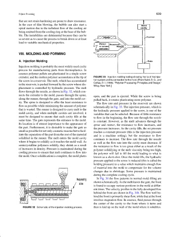
extruder, and the molten polymer accumulates at the tip of FIGURE 33 Injection molding tooling showing the tip of the injec-
the screw in a reservoir. The melt, which has accumulated tion system and its connection to the mold. [From Baird, D. G., and
Collias, D. I. (1998). “Polymer Processing: Principles and Design,”
in the reservoir, is pushed forward by the screw whose dis-
Wiley, New York.]
placement is controlled by hydraulic pressure. The melt
flows through the nozzle, as shown in Fig. 32, which con-
nects the extruder to the mold, passes through the sprue,
open, and the part is ejected. While the screw is being
along the runner, through the gate, and into the mold cav-
pulled back, it rotates plasticating more polymer.
ity. The sprue is designed to offer the least resistance to The flow rate and pressure in the reservoir are shown
flow as possible while minimizing the amount of polymer schematically in Fig. 33. The injection pressure, which is
that is wasted. The runner is designed to carry melt to the the hydraulic pressure applied to the screw, is one of the
mold cavity, and when multiple cavities are involved, it variables that can be selected. Because of little resistance
must be designed to ensure that each cavity fills at the to flow in the beginning, the flow rate through the nozzle
same time. The gate represents the entrance to the mold. is constant. However, as the melt advances through the
Its location is of utmost importance to the appearance of sprue and runner, the resistance to flow increases, and
the part. Furthermore, it is desirable to make the gate as
the pressure increases. As the cavity fills, the set pressure
small as possible for not only cosmetic reasons but to facil-
reaches a constant pressure (this is the injection pressure
itate the separation of the part from the rest of the material
and is a machine setting), but the resistance to flow
solidified in the runner. The melt enters the mold cavity
continues to increase. The flow rate through the nozzle
where it begins to solidify as it touches the mold wall. As
as well as the flow rate into the cavity must decrease. If
semicrystalline polymers solidify, they shrink as a result
the resistance to flow is too great either as a result of the
of increases in density. Pressure is maintained during the
polymer solidifying or the melt viscosity being too high,
cooling process to ensure that melt continues to flow into
the polymer will fail to fill the mold leading to what is
the mold. Once solidification is complete, the mold plates
known as a short-shot. Once the mold fills, the hydraulic
pressure applied to the screw is reduced (this is called the
holding pressure) to a value which maintains enough flow
of material into the mold to compensate for the volume
changes due to shrinkage. Some pressure is maintained
during the complete cooling cycle.
In Fig. 34 the flow patterns in normal mold filling are
shown schematically. As the melt leaves the gate, the front
is found to occupy various positions in the mold at differ-
ent times. The velocity profiles in the fully developed flow
behind the front are shown in Fig. 34b. The flow well be-
hind the front is primarily shear flow, while that at the front
involves stagnation flow. In essence, fluid passes through
the center of the cavity to the front where it turns and
FIGURE 32 Schematic of the injection molding process. then is laid up on the wall of the mold where it solidifies.