
Page 134 - Academic Press Encyclopedia of Physical Science and Technology 3rd Polymer
P. 134
P1: FMX/LSU P2: GPB/GRD P3: GLQ Final pages
Encyclopedia of Physical Science and Technology EN012c-593 July 26, 2001 15:56
640 Polymer Processing
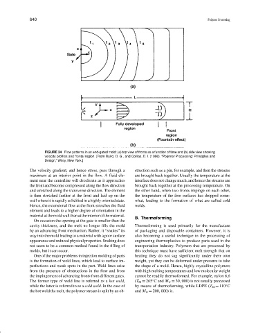
FIGURE 34 Flow patterns in an end-gated mold: (a) top view of fronts as a function of time and (b) side view showing
velocity profiles and frontal region. [From Baird, D. G., and Collias, D. I. (1998). “Polymer Processing: Principles and
Design,” Wiley, New York.]
The velocity gradient, and hence stress, pass through a struction such as a pin, for example, and then the streams
maximum at an interior point in the flow. A fluid ele- are brought back together. Usually the temperature at the
ment near the centerline will decelerate as it approaches interface does not change much, and hence the streams are
the front and become compressed along the flow direction brought back together at the processing temperature. On
and stretched along the transverse direction. The element the other hand, when two fronts impinge on each other,
is then stretched further at the front and laid up on the the temperature of the free surfaces has dropped some-
wall where it is rapidly solidified in a highly oriented state. what, leading to the formation of what are called cold
Hence, the extensional flow at the front stretches the fluid welds.
element and leads to a higher degree of orientation in the
materialatthemoldwallthanattheinteriorofthematerial.
B. Thermoforming
On occasion the opening at the gate is smaller than the
cavity thickness, and the melt no longer fills the mold Thermoforming is used primarily for the manufacture
by an advancing front mechanism. Rather, it “snakes” its of packaging and disposable containers. However, it is
way into the mold leading to a material with a poor surface also becoming a useful technique in the processing of
appearance and reduced physical properties. Snaking does engineering thermoplastics to produce parts used in the
not seem to be a common method found in the filling of transportation industry. Polymers that are processed by
molds, but it can occur. this technique must have sufficient melt strength that on
One of the major problems in injection molding of parts heating they do not sag significantly under their own
is the formation of weld lines, which lead to surface im- weight, yet they can be deformed under pressure to take
perfections and weak spots in the part. Weld lines arise the shape of a mold. Hence, highly crystalline polymers
from the presence of obstructions in the flow and from with high melting temperatures and low molecular weight
the impingement of advancing fronts from different gates. cannot be readily thermoformed. For example, nylon 6,6
◦
The former type of weld line is referred as a hot weld, (T M = 265 C and M w = 30, 000) is not usually processed
◦
while the latter is referred to as a cold weld. In the case of by means of thermoforming, while LDPE (T M = 110 C
the hot weld the melt, the polymer stream is split by an ob- and M w = 200, 000) is.