
Page 192 - Academic Press Encyclopedia of Physical Science and Technology 3rd Polymer
P. 192
P1: GLM Final Pages
Encyclopedia of Physical Science and Technology EN012c-598 July 26, 2001 15:59
Polymers, Mechanical Behavior 701
of convenience, it is common for results to be reported
utilizing the engineering stress in contrast to true stress,
thereby underestimating the actual stress at the time of
failure for materials that show significant deformation.
For specimens that undergo low deformation before
fracture (e.g., glassy polystyrene), the difference between
these two stress parameters is not great and of course
becomes zero in the limit of no deformation. An important
point here is related to the presentation of results; it
would be misleading to report stress arbitrarily without
specifying whether it is engineering stress or true stress.
As will be discussed later, one may often be able to relate
σ t to σ 0 for homogeneous constant volume deformations.
In the case of shear deformation, if simple shear is
imposed, there is no change in the cross-sectional area
and hence only a single stress value must be reported.
This is conventionally denoted by τ (a shear stress) in
contrast to σ (a tensile stress).
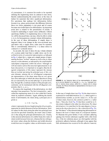
As an aside, the state of stress for any volume element
of a system under load that is under stress can be de-
scribed in terms of a tensorial representation, as indicated
in Fig. 4, where the τ ij terms are a simple means of repre-
senting the three “normal” stresses as well as the six shear
stresses on this element, as indicated by the small double-
subscripted components within the tensor. Although we
will not need to utilize this tensorial representation in our
basic discussions, it is important to recognize that the di-
agonal components of this tensor represent the stresses
that act normal and along the principal axes of this vol-
ume element, whereas the six off-diagonal components
are representative of the shear stress that act on a given
face (first subscript) of which the shear direction is along
the axis denoted by the second subscript. It can be shown FIGURE 4 (a) Tensorial form of the representation of stress
that, through the coordinate rotation of the principle axes, on a volume element of a material; σ 11 , σ 22 , σ 33 , represent ten-
sile or normal stress values, while the τ ij values refer to shear
symmetry can be maintained with the off-diagonal com-
stresses. (b) Three-dimensional representation of stress on a vol-
ponents, that is, τ ij = τ ji . ume element.
To express the magnitude of the deformation, we shall
introduce four parameters. The first is denoted by ε and is
called the engineering strain (it is also called the Cauchy In the case of simple shear (see Fig. 2b) the shear strain is
strain by material scientists). Again, utilizing the tensile expressed for small deformations as x /y, which again is a
mode of deformation, the strain along a principal axis is dimensionless number, as are the values of ε. In the case
given as of shear strain, however, the common symbol is γ rather
than ε. Note also from Fig. 2b that there would be no fi-
ε i = (l i − l 0i )/l 0i , (1)
nite strains induced in the other two directions. For shear
wherel i represents the new length along the ith axis andl 0i deformation, it is noted that for the same degree of move-
represents its initial dimension before deformation. Simi- ment in the shear direction (i.e., the x direction in Fig. 2b),
lar values for the strain along the other two principal axes the “thickness” of the element undergoing deformation in-
can also be specified. Generally, the strain value of inter- fluences the level of shear strain in a reciprocal manner.
est is that along the principal deformation axis. Clearly, To illustrate this point further, if one considers adhering
in the uniaxial deformation of a rubber band, this value of (gluing) two broken substrates together with a thin bond
strain would increase from zero, whereas the two orthogo- line, if the two substrate pieces are slid together with the
nal strain values along the thickness and width direction polymeric adhesive between, although it may appear that
would decrease to negative values as deformation occurs. little deformation has occurred for the adhesive material,