
Page 161 - Engineered Interfaces in Fiber Reinforced Composites
P. 161
Chapter 4. Micromechanics of stress transfer I43
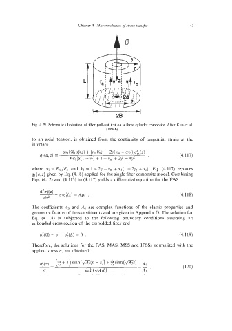
Fig. 4.29. Schematic illustration of fiber pull-out test on a three cylinder composite. After Kim et al.
(l994b).
to an axial tension, is obtained from the continuity of tangential strain at the
interface
(4.117)
where cq = E,/Ec and kl = 1 + 2y - v, + a1 (1 + 2yl + vc). Eq. (4.1 17) replaces
ql (a, z) given by Eq. (4.18) applied for the single fiber composite model. Combining
Eqs. (4.12) and (4.1 13) to (4.117) yields a differential equation for the FAS
(4.118)
The coefficients A3 and A4 are complex functions of the elastic properties and
geometric factors of the constituents and are given in Appendix D. The solution for
Eq. (4.1 18) is subjcctcd to the following boundary conditions assuming an
unbonded cross-section of the embedded fiber end
rq0) = 0, cr',(L) = 0 . (4.1 19)
Therefore, the solutions for the FAS, MAS, MSS and IFSSs normalized with the
applied stress 0, are obtained:
@+ 1) sinh[fi(L -z)] +%sinh(&z)
-- $(z) - --
d sinh (&L) A3 '